A porous ceramic dust collector

A technology for porous ceramics and dust collectors, applied in chemical instruments and methods, dispersed particle separation, dispersed particle filtration, etc., can solve problems such as cracks in the head of the porous ceramic tube, complex nozzle installation structure, affecting stable operation, etc. Filtration rate, simple structure, good reliability

Active Publication Date: 2018-09-11
HUNAN CHANGZHONG MACHINERY
View PDF7 Cites 0 Cited by
  • Summary
  • Abstract
  • Description
  • Claims
  • Application Information

AI Technical Summary

Problems solved by technology

[0005] In order to solve the technical problem that the possible clogging of the porous ceramic tube during operation may affect the operation of the system in the prior art, as well as the cracks at the head of the porous ceramic tube caused by the change of heating and cooling temperature during the installation of the porous ceramic tube, and the brittleness of the porous ceramic tube fracture, which affects stable operation, and the installation structure of the nozzle is relatively complicated, the reliability is poor, and the installation is difficult. flow

Method used


Image

  • A porous ceramic dust collector
  • A porous ceramic dust collector
  • A porous ceramic dust collector

Examples


Embodiment 1

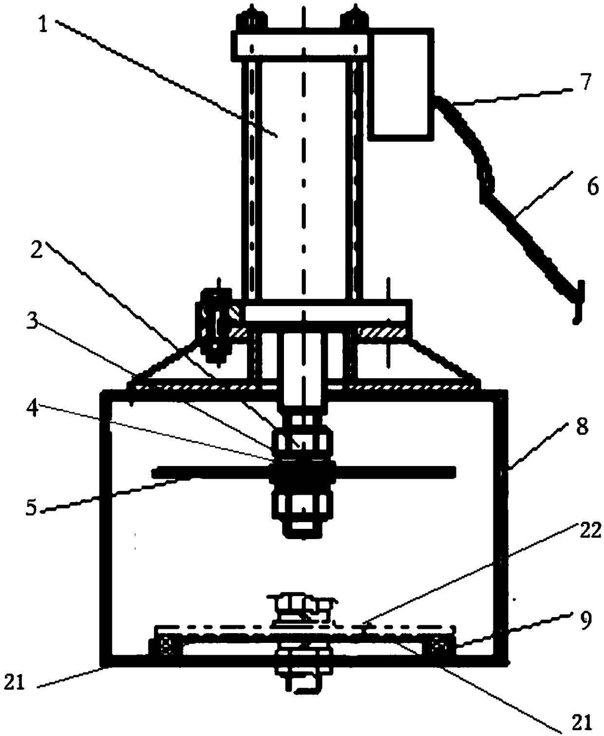
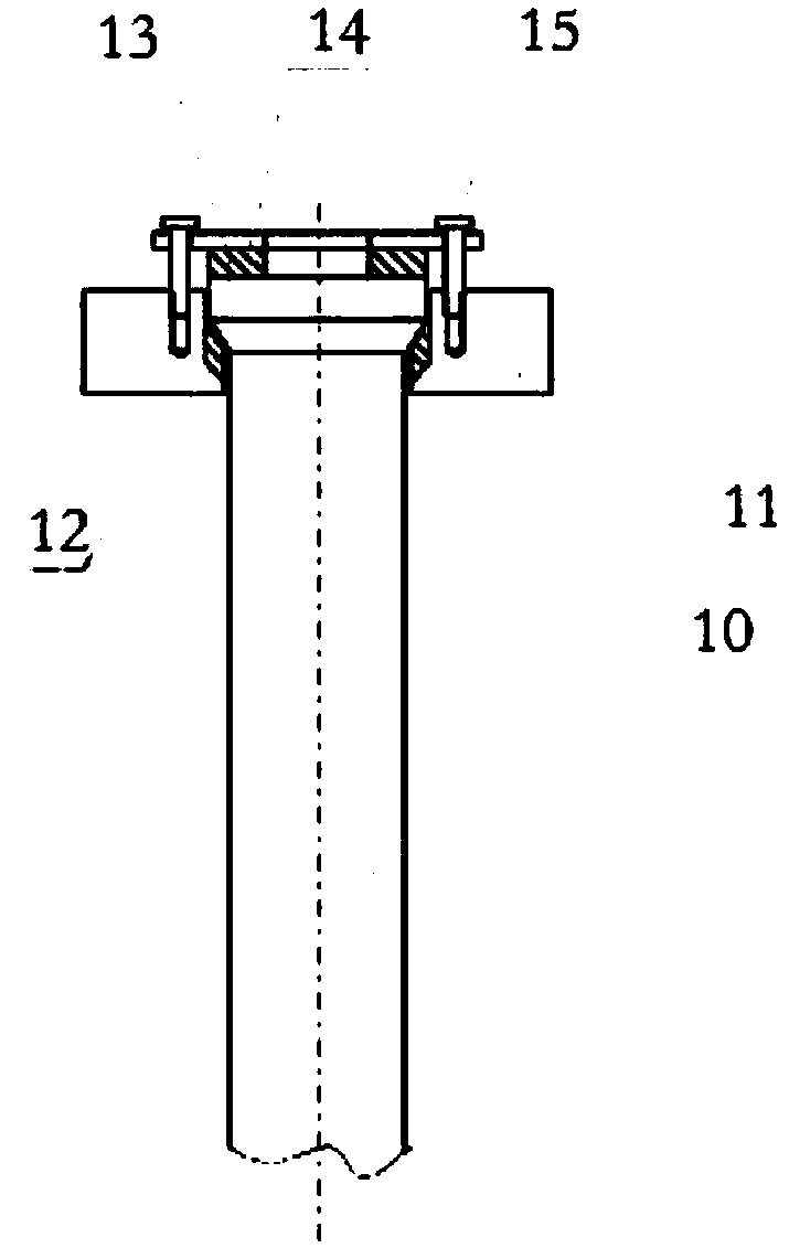
[0020] Embodiment 1: A kind of porous ceramic dust collector, the porous ceramic filter core is arranged between the inlet and the outlet of the dust collector, it is characterized in that it also includes an emergency bypass device, an installation fixing device and a quick connection device, wherein the emergency bypass device is provided with A valved cylinder (1) equipped with a solenoid valve, a valve plate (5) is arranged at the bottom of the cylinder; the valve plate (5) is fixed by a nut (2), a flat washer (3), and a spring washer (4). Trachea (6) and copper gas nozzle (7). The valved cylinder is installed on the base (8), and there are air holes on both sides of the base (8), and a circular graphite gasket (9) for sealing is arranged around the bypass hole (21) of the partition; the porous ceramic tube in the installation and fixing device (10) One end is an arc-shaped transition, and the tube sealing gasket (12) is made of graphite material, which is made into a doub...

Embodiment 2

[0023] Embodiment 2: A kind of porous ceramic dust collector, a porous ceramic filter element is arranged between the inlet and the outlet of the dust collector, and it is characterized in that it also includes an emergency bypass device, a mounting fixture and a quick connection device, wherein the emergency bypass device is provided with A valved cylinder (1) equipped with a solenoid valve, a valve plate (5) is arranged at the bottom of the cylinder; the valve plate (5) is fixed by a nut (2), a flat washer (3), and a spring washer (4). Trachea (6) and copper gas nozzle (7). The valved cylinder is installed on the base (8), and there are air holes on both sides of the base (8), and a circular graphite gasket (9) for sealing is arranged around the bypass hole (21) of the partition; the porous ceramic tube in the installation and fixing device (10) One end is an arc-shaped transition, and the tube sealing gasket (12) is made of graphite material, which is made into a double arc...


PUM


Abstract

A porous ceramic dust collector, including an emergency bypass device, a mounting fixture and a quick connection device, wherein the emergency bypass device is equipped with a valved cylinder with a solenoid valve, a valve plate is provided at the bottom of the cylinder, and an air inlet pipe and copper gas are provided at the top of the cylinder Nozzle, the cylinder with valve is installed on the base, there are air holes on both sides of the base, and a circular graphite pad for sealing is arranged around the bypass hole of the partition; one end of the porous ceramic tube in the installation and fixing device is an arc-shaped transition, and the tube sealing pad It is made into a double arc shape with a certain gap with the porous ceramic tube, and it is attached to the tube flower plate and the porous ceramic tube. The top of the porous ceramic tube is equipped with a graphite flat washer, and the tube pressure plate is fixed on the tube flower plate by bolts. ; One end of the spray elbow in the quick connection device is welded to a connection end with a tapered structure, and the same end of the long nozzle with a nozzle is welded to the connection end. The hoop is connected and locked, and a sealing ring is arranged between the spray elbow and the long nozzle.

Description

technical field [0001] The invention relates to a flue gas dedusting device, in particular to a porous ceramic deduster. Background technique [0002] Porous ceramic dust collector has outstanding advantages such as high temperature resistance, corrosion resistance, cleaning resistance, high mechanical strength, stable structure without deformation and long life, so it is considered to be the best choice for hot particle filter materials. The porous ceramic dust collector has high separation efficiency, and the dust removal rate can generally exceed 99.99%. Its filtration performance, especially for fine particle filtration below PM2.5, is unmatched by other dust removal and dust collection equipment. In addition, the microporous ceramic filter membrane will not produce secondary pollution, and is the most suitable and promising method for various waste gas treatment. [0003] However, because the sintering flue gas in many industries has the characteristics of high emissio...

Claims


Application Information

Patent Timeline
Patent Type & Authority Patents(China)
IPC IPC(8): B01D46/24B01D46/44B01D46/00
CPCB01D46/0087B01D46/24B01D46/44B01D46/762B01D46/76
Inventor 文向前吴海燕曾文凤
Owner HUNAN CHANGZHONG MACHINERY
Why Eureka
Try Eureka