Packing box cover fastening structure

A packaging box and box cover technology, applied in the field of packaging boxes, can solve the problems of complex production process, unfavorable packaging box appearance, generous, simple, unfavorable recycling, etc., and achieve full creative effect

Active Publication Date: 2016-08-17
SHANTOU TIMSE PACKING LTD +1
View PDF6 Cites 0 Cited by
  • Summary
  • Abstract
  • Description
  • Claims
  • Application Information

AI Technical Summary

Problems solved by technology

[0004] The lid fastening mechanism of the existing rotary connection type packaging box usually adopts magnet blocks 41, 42 (or metal buttons), such as figure 1 As shown, there are the following problems: one, the front edge of the box cover must be provided with a rotatable dash panel 4, which not only wastes materials, but also is not conducive to the beauty, generosity and simplicity of the front of the whole packaging box; two, the production process is complicated, and the magnet block 41, 42 (or metal buttons) need to be attached to the front wall of the box body and the dash panel 5 through complicated processes, and it is difficult to form a firm connection between the magnet blocks 41, 42 (or metal buttons) and the cardboard; 3. When the packaging carton is invalid and the paper needs to be recycled, the magnet blocks 41, 42 (or metal buttons) are difficult to take out with bare hands. If the magnet blocks 41, 42 (or metal buttons) are not taken out, the entire packaging carton is difficult to crush process, not conducive to recycling

Method used


Image

  • Packing box cover fastening structure
  • Packing box cover fastening structure
  • Packing box cover fastening structure

Examples


Embodiment 1

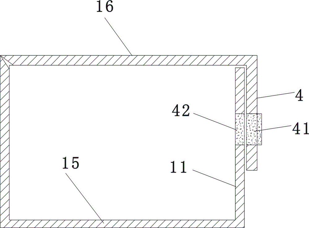
[0046] figure 2 , Figure 5 , Figure 6 , Figure 7 The lid fastening structure of a packaging box shown includes a box body made of cardboard and a lid 16. The lid 16 is flat, and the box body is provided with a bottom 12, a front wall 11, a rear wall, and a right side wall. 14. The left side wall (not shown in the figure, located on the side opposite to the right side wall), the rear wall of the box body includes two layers, the inner layer rear wall 121 and the left side wall, the right side wall 14 and the The bottom of the box 15 forms a fixed connection, and the rear edge of the lid 16 is relatively rotatably connected with the upper edge of the outer layer rear wall 122, and the lower edge of the outer layer rear wall 122 and the rear edge of the box bottom 15 can be connected between the two. Relatively rotationally connected.

[0047] figure 2 , image 3 , Figure 4 , Figure 5 , Figure 6 , Figure 7 As shown, the front end of the lid 16 is provided with ...

Embodiment 2

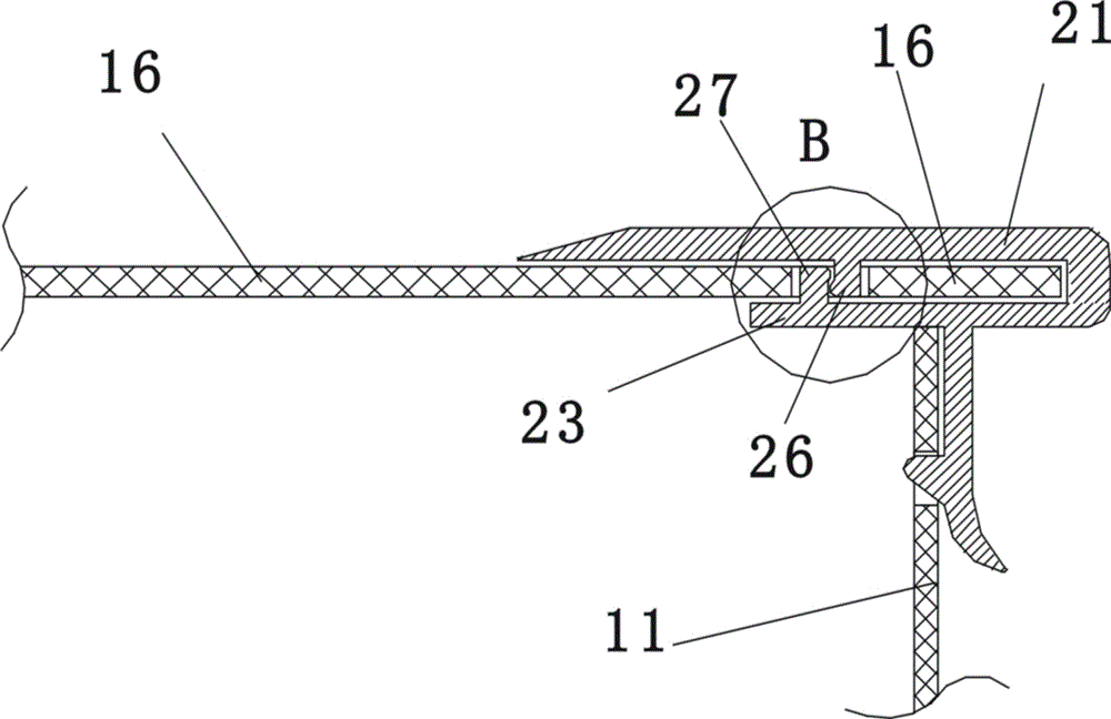
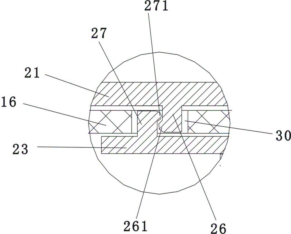
[0051] The difference between the second embodiment and the first embodiment lies in the following two points: 1. In the second embodiment, the locking clip is made of light metal material. 2. In the second embodiment, the horizontal positions of the lower bump 27 and the upper bump 26 are close together, such as Figure 10 , Figure 11 As shown, the lower end of the upper protrusion 26 forms a first flange 261 protruding in the horizontal direction, and the upper end of the lower protrusion 27 forms a second flange 271 protruding in the horizontal direction. above the first flange 261, so that the second flange 271 and the first flange 261 are locked together vertically; the central part of the front end of the lid is only provided with an assembly for the upper projection 26 and the lower projection to embed. Button hole 30 , the upper bump and the lower bump are inserted in the overall button hole 30 . All the other are the same as the first embodiment.

[0052] Embodime...

Embodiment 3

[0054] The difference between the third embodiment and the second embodiment is that in the third embodiment, the lower horizontal sheet 23 is provided with two lower bumps 27 arranged side by side, as Figure 12 , Figure 13 As shown, the longitudinal gap between the two lower projections 27 is formed as a clamping opening 29, and an upper projection 26 of the upper horizontal sheet 21 is tightly fitted into the clamping opening 29, and the first flange of the upper projection 26 261 and the second flange 271 of the lower projection 27 form a vertical clamping force; the upper projection 26 and the two lower projections 27 are all inserted in the total button hole 30, as Figure 12 , Figure 13 shown. All the other are identical with embodiment two.

[0055] Embodiment 3 In the assembly process, only the lower horizontal sheet 23 and the upper horizontal sheet 21 need to be separated (the splitting process is as follows: Figure 13 As shown, the breaking process overcomes...


PUM


Abstract

The invention provides a packing box cover fastening structure which comprises a box body and a box cover made of paperboards. The front end of the box cover is provided with a lock buckle clamp; the lock buckle clamp comprises an upper horizontal piece, a vertical turning segment, a lower horizontal piece and a lock buckle piece which are connected into a whole, the upper horizontal piece, the lower horizontal piece and the vertical turning segment are connected to form a U-shaped horizontal clamp groove, and the center of the front end of the box cover is inserted into the U-shaped horizontal clamp groove; an upper protrusive block protruding downwards is integrally formed on the lower surface of the upper horizontal piece, a lower protrusive block protruding upwards is integrally formed on the upper surface of the lower horizontal piece, and a first buckle hole for allowing the upper protrusive block to embed and a second buckle hole for allowing the lower protrusive block to embed are formed in the center of the front end of the box cover; the lock buckle piece is integrally provided with a back protrusive block protruding backwards; when the box cover is closed in a covering mode, the back protrusive block of the lock buckle piece is bucked into a third buckle hole. According to the packing box cover fastening structure, assembly is easy and convenient, connection among the components is firm, and the action process of fastening the box cover or opening the box cover is convenient.

Description

technical field [0001] The invention belongs to the technical field of packaging boxes, and in particular relates to a fastening structure for a lid of a packaging box. Background technique [0002] Distinguished from the connection form of the box cover and the box body, the packaging box can be divided into two types. The first type is a split type in which the box cover and the box body can be separated. For the box cover, remove the whole box cover from the box body; the second is the rotary connection type in which the box cover and the box body cannot be separated. The box body and box cover of the rotary connection type packaging box are usually made of cardboard. The cover is usually only composed of a flat cover surface (no vertical cover edge is provided), and the rear end of the cover is rotatably connected to the rear wall of the box body through the crease line. [0003] Compared with the split-type packaging box, it is convenient and quick to lift the box cove...

Claims


Application Information

Patent Timeline
IPC IPC(8): B65D45/22
CPCB65D45/22
Inventor 柯勇
Owner SHANTOU TIMSE PACKING LTD
Why Eureka
Try Eureka