Box cover fastening structure
A box cover and box body technology, applied in the field of fastening structure of the box cover of the packaging box, can solve the problems of complex production process, difficult crushing process of the packaging carton, difficult to form a fastening connection, etc., and achieve full creative effect
- Summary
- Abstract
- Description
- Claims
- Application Information
AI Technical Summary
Problems solved by technology
Method used
Image
Examples
Embodiment 1
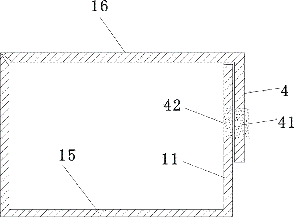
[0046] figure 2 , Figure 5 , Figure 6 , Figure 7 The lid fastening structure of a packaging box shown includes a box body made of cardboard and a lid 16. The lid 16 is flat, and the box body is provided with a bottom 12, a front wall 11, a rear wall, and a right side wall. 14. The left side wall (not shown in the figure, located on the side opposite to the right side wall), the rear wall of the box body includes two layers, the inner layer rear wall 121 and the left side wall, the right side wall 14 and the The bottom of the box 15 forms a fixed connection, and the rear edge of the lid 16 is relatively rotatably connected with the upper edge of the outer layer rear wall 122, and the lower edge of the outer layer rear wall 122 and the rear edge of the box bottom 15 can be connected between the two. Relatively rotationally connected.
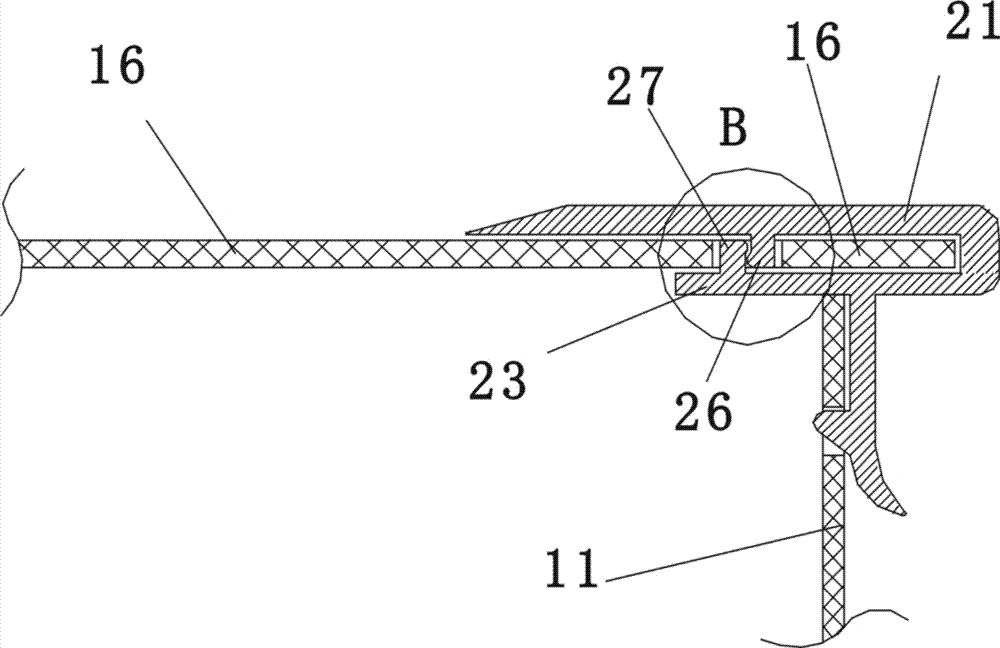
[0047] figure 2 , image 3 , Figure 4 , Figure 5 , Figure 6 , Figure 7 As shown, the front end of the lid 16 is provided with ...
Embodiment 2
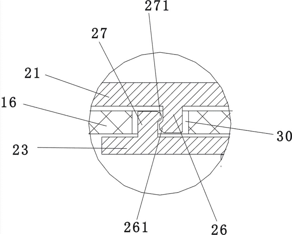
[0051] The difference between the second embodiment and the first embodiment lies in the following two points: 1. In the second embodiment, the locking clip is made of light metal material. 2. In the second embodiment, the horizontal positions of the lower bump 27 and the upper bump 26 are close together, such as Figure 10 , Figure 11 As shown, the lower end of the upper protrusion 26 forms a first flange 261 protruding in the horizontal direction, and the upper end of the lower protrusion 27 forms a second flange 271 protruding in the horizontal direction. above the first flange 261, so that the second flange 271 and the first flange 261 are locked together vertically; the central part of the front end of the lid is only provided with an assembly for the upper projection 26 and the lower projection to embed. Button hole 30 , the upper bump and the lower bump are inserted in the overall button hole 30 . All the other are the same as the first embodiment.
[0052] Embodime...
Embodiment 3
[0054] The difference between the third embodiment and the second embodiment is that in the third embodiment, the lower horizontal sheet 23 is provided with two lower bumps 27 arranged side by side, as Figure 12 , Figure 13 As shown, the longitudinal gap between the two lower projections 27 is formed as a clamping opening 29, and an upper projection 26 of the upper horizontal sheet 21 is tightly fitted in the clamping opening 29, and the first flange of the upper projection 26 261 and the second flange 271 of the lower projection 27 form a vertical clamping force; the upper projection 26 and the two lower projections 27 are all inserted in the total button hole 30, as Figure 12 , Figure 13 shown. All the other are identical with embodiment two.
[0055] Embodiment 3 In the assembly process, only the lower horizontal sheet 23 and the upper horizontal sheet 21 need to be separated (the splitting process is as follows: Figure 13 As shown, the breaking process overcomes t...
PUM
 Abstract
Description
Claims
Application Information
 - R&D
- Intellectual Property
- Life Sciences
- Materials
- Tech Scout
- Unparalleled Data Quality
- Higher Quality Content
- 60% Fewer Hallucinations
Browse by: Latest US Patents, China's latest patents, Technical Efficacy Thesaurus, Application Domain, Technology Topic, Popular Technical Reports.
© 2025 PatSnap. All rights reserved.Legal|Privacy policy|Modern Slavery Act Transparency Statement|Sitemap|About US| Contact US: help@patsnap.com


