
Dual-drive automatic tube penetrating machine and method

A technology of automatic pipe threading machine and driving mechanism, which is applied to bridge parts, erecting/assembling bridges, bridges, etc. It can solve the problems of insufficient clamping force of the transmission sleeve, insufficient overall driving force, slipping of rubber rods, etc., and achieves a small number , The performance is safe and reliable, and the effect of preventing lateral slippage

Inactive Publication Date: 2016-08-17
朱学德
View PDF1 Cites 1 Cited by
  • Summary
  • Abstract
  • Description
  • Claims
  • Application Information

AI Technical Summary

Problems solved by technology

[0002] During the construction of prefabricated bridges, rubber tubes can be used to pull out the prestressed tension channels to form holes for subsequent steel strands to be threaded and prestressed. If the rubber tubes are not linearly smooth during installation, the prestressed cause great loss
At present, in the construction of bridge engineering, the installation of prefabricated beam hole hole-forming rubber rods mainly adopts the manual penetration installation method, that is, the hole-forming rubber tubes are manually transported to the two ends of the steel skeleton, guided by one person, and 8 to 10 people are required to manually install the holes. The rubber tube is penetrated into the channel, which has the disadvantages of high labor intensity, low work efficiency index, and the need to build a working platform for the high-level channel, which is unsafe to operate.
[0003] The Chinese patent announcement number is 204982667 and the U application number is 201520425379.0, which discloses a pipe threading machine including a support, a plurality of rollers, two moving rails, a lifting motor, a lifting frame, a mounting frame, a steel wire rope, a pressing motor, and a plurality of transmission sleeves Sleeve, connecting sleeve, transmission motor, motor support plate, sleeve fixing plate and lead screw, the inventor considered that the clamping force of the transmission sleeve is insufficient, and increased the number and set up a plurality of them, but the driven sleeve is only passive Rotation, the overall driving force is insufficient, and there is still the problem that the rubber rod slips laterally from the two drive rollers

Method used


Image

  • Dual-drive automatic tube penetrating machine and method
  • Dual-drive automatic tube penetrating machine and method
  • Dual-drive automatic tube penetrating machine and method

Examples


Embodiment Construction

[0031] The present invention will be described in detail below in conjunction with the accompanying drawings and specific embodiments.

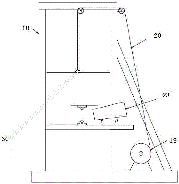
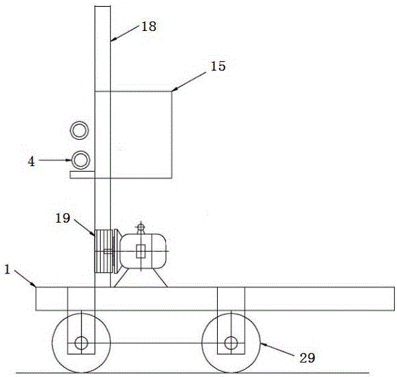
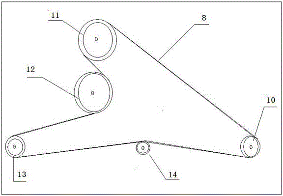
[0032] As shown in the figure, a double-drive automatic pipe threading machine provided by the present invention includes a support 1, a driving mechanism and a steel chuck 2, including an upper driving wheel 3 and a lower driving wheel 4, and an upper driving wheel 3 and a lower driving wheel 4. The upper and lower driving wheels are opposite and the axial directions are on the same vertical plane. The middle part of the upper driving wheel 3 and the lower driving wheel 4 has a concave arc 5. The two concave arcs are used to accommodate and clamp rubber rods. The driving motor drives the upper driving wheel 3 and the lower driving wheel 4 rotate simultaneously in the opposite direction. The steel chuck 2 is installed on the front end of the rubber rod. The lower part of the steel chuck 2 is provided with a roller 6 and a telescopic support ar...


PUM


Abstract

The invention discloses a double-drive automatic pipe threading machine, which includes a support, a driving mechanism and a steel chuck. On the same vertical plane, there is a concave arc in the middle of the upper driving wheel and the lower driving wheel, and the upper and lower opposite concave arcs are used to accommodate and clamp the rubber rod, and the driving motor drives the upper driving wheel and the lower driving wheel to rotate in opposite directions at the same time ,The drive shaft of the drive mechanism is equipped with an oil seal, which can reduce labor intensity, prevent lateral slippage and drive strongly.

Description

technical field [0001] The invention belongs to the technical field of prefabricated bridge construction equipment, in particular to a dual-drive automatic pipe threading machine. Background technique [0002] During the construction of prefabricated bridges, rubber tubes can be used to pull out the prestressed tension channels to form holes for subsequent steel strands to be threaded and prestressed. If the rubber tubes are not linearly smooth during installation, the prestressed cause great loss. At present, in the construction of bridge engineering, the installation of prefabricated beam hole hole-forming rubber rods mainly adopts the manual penetration installation method, that is, the hole-forming rubber tubes are manually transported to the two ends of the steel skeleton, guided by one person, and 8 to 10 people are required to manually install the holes. The rubber tube is penetrated into the channel, and this method has the disadvantages of high labor intensity, low...

Claims


Application Information

Patent Timeline
IPC IPC(8): E01D21/00E01D19/00E04G21/12
CPCE01D21/00E01D19/00E04G21/12
Inventor 朱学德
Owner 朱学德
Features
  • Generate Ideas
  • Intellectual Property
  • Life Sciences
  • Materials
  • Tech Scout
  • Unparalleled Data Quality
  • Higher Quality Content
  • 60% Fewer Hallucinations
Learn More