
Gasoline steam purification device utilizing electric magnetism-generating transmission principle

A technology of steam purification and gasoline, which is applied in the direction of charging system, engine components, machines/engines, etc., and can solve the problems of low negative pressure, waste of resources, and less volatile emissions of gasoline

Active Publication Date: 2016-08-17
NINGBO TUOPU INTELLIGENT BRAKE SYST
View PDF6 Cites 0 Cited by
  • Summary
  • Abstract
  • Description
  • Claims
  • Application Information

AI Technical Summary

Problems solved by technology

[0002] With more and more cars with turbochargers on the market, the negative pressure of the turbocharger is lower than that of the naturally aspirated intake manifold, and the oil vapor collected by the carbon canister cannot be directly sucked into the intake manifold, so that the carbon After the tank collects oil vapor, it cannot be discharged, and the oil vapor cannot be fully utilized, resulting in waste of resources. If the carbon tank is full of oil vapor and cannot be discharged, it will be dangerous. In addition, my country will implement the National VI emission standard for engines in 2019, requiring gasoline less volatile emissions

Method used


Image

  • Gasoline steam purification device utilizing electric magnetism-generating transmission principle
  • Gasoline steam purification device utilizing electric magnetism-generating transmission principle
  • Gasoline steam purification device utilizing electric magnetism-generating transmission principle

Examples


Embodiment Construction

[0016] Below in conjunction with specific embodiment, further illustrate the present invention. It should be understood that these examples are only used to illustrate the present invention and are not intended to limit the scope of the present invention. In addition, it should be understood that after reading the teachings of the present invention, those skilled in the art can make various changes or modifications to the present invention, and these equivalent forms also fall within the scope defined by the appended claims of the present application.

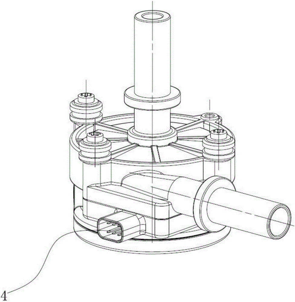
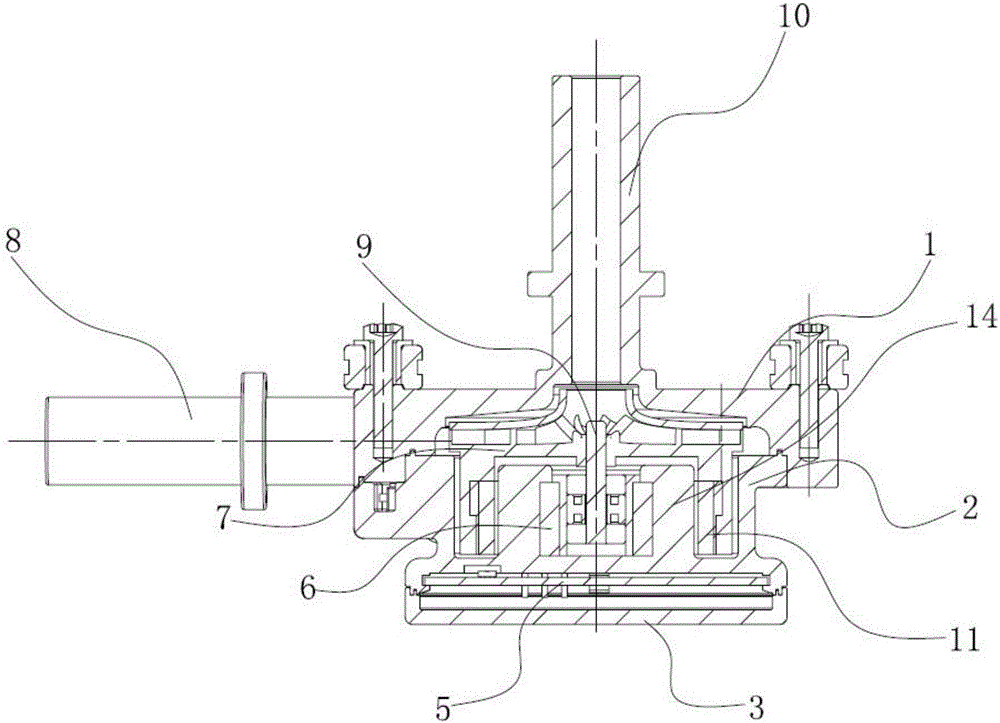
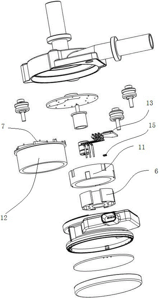
[0017] Such as Figure 1-3 As shown, the embodiment of the present invention relates to a gasoline vapor purification device adopting energization and magnetic transmission, including a volute 1, an impeller 7 and a casing 2, the upper end of the casing 2 is connected with the volute 1, and the The inner bottom of the housing 2 is centered with a cylindrical partition 14, the inside of the cylindrical partition 14 is installed...


PUM


Abstract

The invention relates to a gasoline steam purification device utilizing an electric magnetism-generating transmission principle. The gasoline steam purification device utilizing the electric magnetism-generating transmission principle comprises a volute, an impeller and a shell. The upper end of the shell is connected with the volute. A cylindrical partition plate is arranged in the middle of the inner bottom of the shell. A stator is installed inside the cylindrical partition plate. The magnetic impeller arranged coaxially with the stator is installed in the position, above the cylindrical partition plate, of the volute in a rotating mode. An air intake pipe is vertically arranged in the position, corresponding to the center of the magnetic impeller, of the upper end of the volute. An air exhaust pipe is arranged on the side wall of the volute in the tangent direction of the magnetic impeller. A bottom cover is installed at the bottom of the shell. A PCB is installed between the bottom cover and the shell. A magnetic field is generated inside the gasoline steam purification device through the electric magnetism-generating principle, the magnetic impeller is driven to rotate by the magnetic field, and accordingly pressure difference is formed; and oil steam collected by a carbon tank is fed into an air intake manifold and prevented from being exhausted into air, and the requirement for emission reduction is met accordingly.

Description

technical field [0001] The invention relates to the technical field of purifying devices, in particular to a gasoline vapor purifying device adopting energized magnetic drive. Background technique [0002] As there are more and more cars with turbochargers on the market, the negative pressure of the turbocharged intake manifold is lower than that of the naturally aspirated intake manifold, and the oil vapor collected by the carbon canister cannot be directly sucked into the intake manifold, so that the carbon After the tank collects oil vapor, it cannot be discharged, and the oil vapor cannot be fully utilized, resulting in waste of resources. If the carbon tank is full of oil vapor and cannot be discharged, it will be dangerous. In addition, my country will implement the National VI emission standard for engines in 2019, requiring gasoline Less volatile emissions. In order to solve the above problems, a device that sucks oil vapor from the carbon canister to the intake manif...

Claims


Application Information

Patent Timeline
Patent Type & Authority Applications(China)
IPC IPC(8): F02M25/08
CPCF02M25/08
Inventor 蒋开洪杨木
Owner NINGBO TUOPU INTELLIGENT BRAKE SYST
Learn More