
Object size measurement method and image database data acquisition method

A measurement method and technology of physical size, applied in measurement devices, electrical digital data processing, special data processing applications, etc., can solve the problems of complexity, limited scope of use, manual error-prone, etc. Effect

Inactive Publication Date: 2016-08-17
CHENGDU IDEALSEE TECH
View PDF5 Cites 36 Cited by
  • Summary
  • Abstract
  • Description
  • Claims
  • Application Information

AI Technical Summary

Problems solved by technology

[0002] In the field of content-based image recognition and augmented reality technology, it is usually necessary to collect image data in advance to establish an image database. The conventional method is to take pictures of the objects to be collected one by one and store them in the database. If it is necessary to add other parameters of the object to the database, such as size, Size, etc., usually need to be manually measured, and then manually matched to the photo input, manual measurement and input work is very heavy, and manual error-prone
[0003] In terms of object size measurement, there are studies on the size of large objects in the prior art, for example: "Shi Mengmeng, Han Yan, Wang Jian, etc. Research on 3D Measurement Method of Large Object Size Based on Image, Computer Measurement and Control, 2011019( 10): 2351-2353", when measuring the size of a large object mentioned in this article, it is necessary to adaptively find a calibration template from the object itself, and then manually measure the size of the calibration template. Every time an object is measured, it is necessary to manually measure the calibration template once , this method has no problem in measuring large objects, but if it is applied to the measurement of a large number of ordinary objects, it is more complicated than manual direct measurement, and it is not suitable for objects with no significant features on the surface of the target measurement object. Possibility to calibrate the template, so this method has limited scope

Method used


Image

  • Object size measurement method and image database data acquisition method
  • Object size measurement method and image database data acquisition method
  • Object size measurement method and image database data acquisition method

Examples


Embodiment Construction

[0025] The following will clearly and completely describe the technical solutions in the embodiments of the present invention with reference to the accompanying drawings in the embodiments of the present invention. Obviously, the described embodiments are only some, not all, embodiments of the present invention. Based on the embodiments of the present invention, all other embodiments obtained by persons of ordinary skill in the art without creative efforts fall within the protection scope of the present invention.

[0026] The template image of the present invention: refers to the image used for identification, here refers to the digital image, stored in the system, and is the storage image of the calibration map;

[0027] The calibration map in the present invention can be understood as a picture printed from the template image, which is printed or pasted on the surface of a rigid plane object to form one of the calibration objects.

[0028] see figure 1 , is a schematic flo...


PUM


Abstract

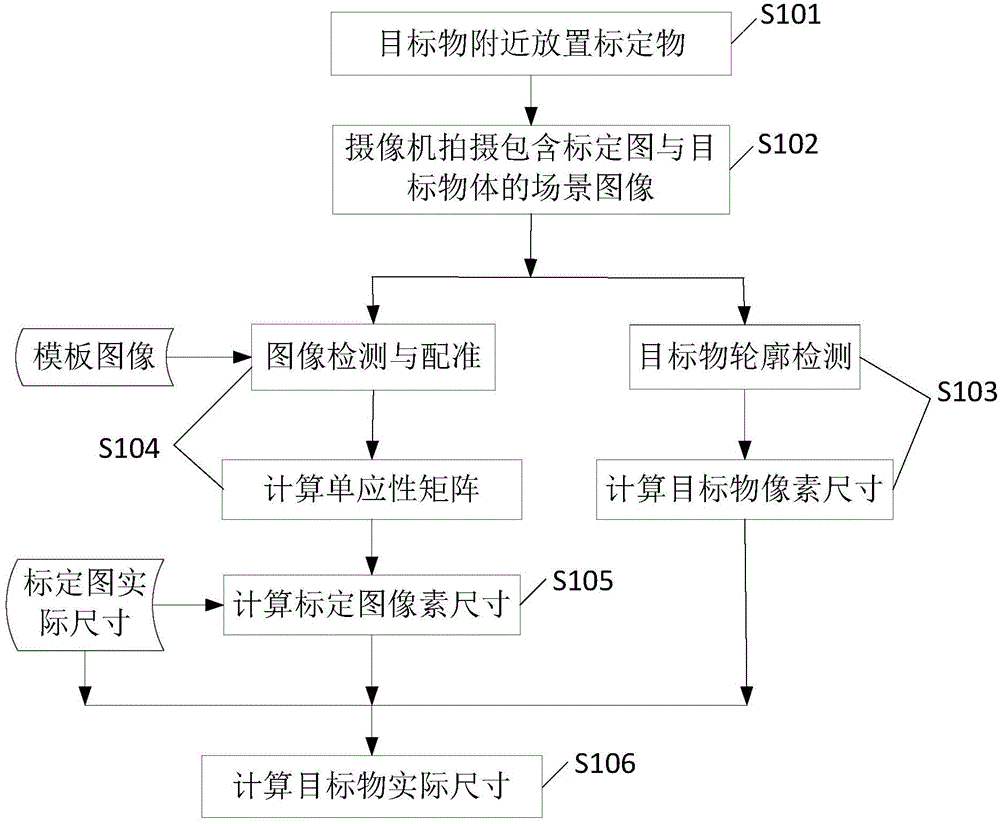
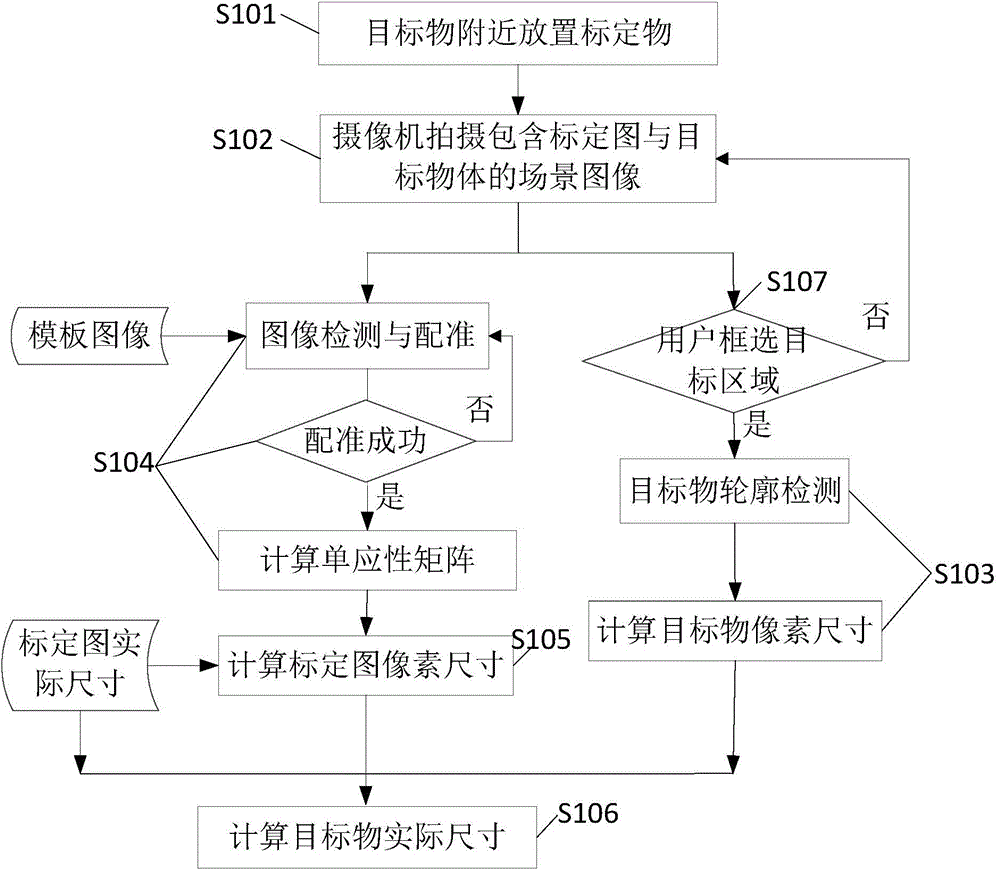
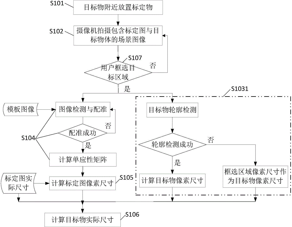
The invention discloses an object size measurement method. A calibration object is placed near a target object, pixel sizes of the target object and the calibration object are calculated, the actual size of the target object is calculated, no measurement tool is needed, and the external size of a general object can be quickly and accurately measured. Meanwhile, the invention also discloses an image database data acquisition method based on the object size measurement method. When a database comprising a target object image sample and the size of the target object is built, automatic database construction can be realized, that is, the target object image sample and the size can be obtained at the same time at one time through photographing, corresponding database construction is realized, and compared with manual recording, the method of the invention is labor-saving and time-saving, and is less error-prone.

Description

technical field [0001] The invention relates to the field of data collection, in particular to a method for measuring physical dimensions and a data collection method for an image database. Background technique [0002] In the field of content-based image recognition and augmented reality technology, it is usually necessary to collect image data in advance to establish an image database. The conventional method is to take pictures of the objects to be collected one by one and store them in the database. If it is necessary to add other parameters of the object to the database, such as size, Size, etc., usually need to be manually measured, and then manually matched to the photo input, manual measurement and input work is very heavy, and manual error-prone. [0003] In terms of object size measurement, there are studies on the size of large objects in the prior art, for example: "Shi Mengmeng, Han Yan, Wang Jian, etc. Research on 3D Measurement Method of Large Object Size Base...

Claims


Application Information

Patent Timeline
Patent Type & Authority Applications(China)
IPC IPC(8): G01B11/00G01B11/24G06F17/30
Inventor 柳寅秋宋海涛刘洋
Owner CHENGDU IDEALSEE TECH
Learn More