
Gas leak detection non-uniform correction method and gas leak detection device

A gas leak detection and non-uniform correction technology, applied in the field of data identification, can solve problems such as poor effect and large temperature difference, and achieve the effects of improving detection accuracy, improving non-uniform correction effect, and improving gas non-uniform correction effect.

Active Publication Date: 2018-06-29
CHINA SAFETY TECH OPTOELECTRONICS CO LTD SHANDONG
View PDF7 Cites 0 Cited by
  • Summary
  • Abstract
  • Description
  • Claims
  • Application Information

AI Technical Summary

Problems solved by technology

For the field of gas leak detection, equipment pipelines and leaking gas have high temperature, while the temperature of the external environment is low, and there is often a large temperature difference in an image. For a frame of infrared image with a large temperature difference, the above method is used to perform non-uniform Correction effect is poor

Method used


Image

  • Gas leak detection non-uniform correction method and gas leak detection device
  • Gas leak detection non-uniform correction method and gas leak detection device
  • Gas leak detection non-uniform correction method and gas leak detection device

Examples


Embodiment 1

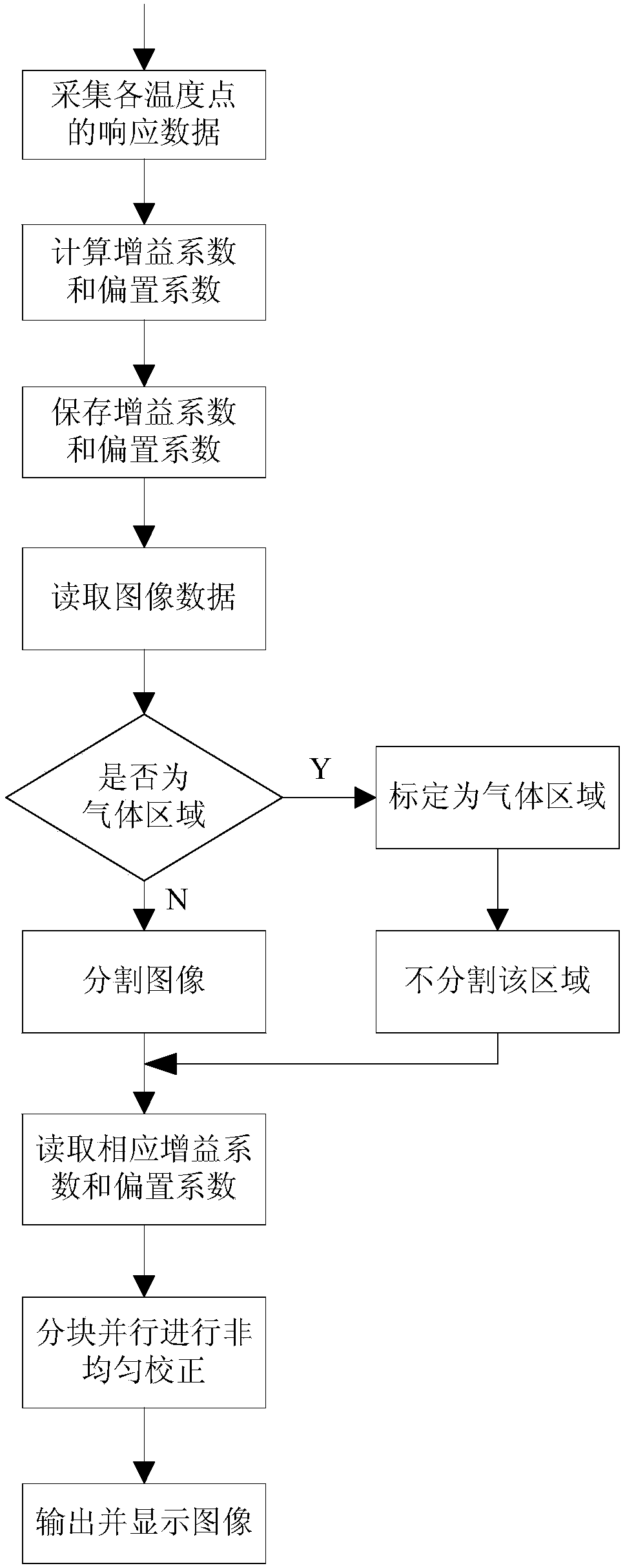
[0045] Such as figure 1 As shown, the non-uniform correction method for gas leakage detection in the present invention includes the following steps:

[0046] Step 1: Collect the response data of each photosensitive element of the infrared image sensor at each temperature value, and use the two-point correction method to calculate the gain coefficient G of each temperature segment using formula (1) and formula (2). ij and bias coefficient Q ij ,

[0047]

[0048]

[0049] where Xij (H) and X ij (L) are the responses of pixel (i, j) under high temperature and low temperature uniform radiation background respectively, V H and V L are the average output of all pixels in the focal plane array, respectively;

[0050] Step 2, for the gain coefficient G of each temperature section ij and bias coefficient Q ij store separately;

[0051] Step 3, the gas leakage detection device reads the gain coefficient G of each temperature section ij and bias coefficient Q ij ;

[00...

Embodiment 2

[0069] Such as Figure 4-6 This embodiment provides a gas leakage detection device on the basis of Embodiment 1, including a housing 1, a main control chip is arranged in the housing 1, and the main control chip is connected to an infrared imaging module, a display module and a power module 2, and the power module 2 supplying power to the remaining modules, the infrared imaging module includes an infrared lens 3 arranged in sequence, an infrared window 4 and an infrared image sensor, the infrared image sensor is arranged inside the casing 1, Figure 4-6 are not shown.

[0070] The display module includes an ordinary display module 5 and a strong light display module 6, the ordinary display module 5 is hinged to the housing 1, the back of the ordinary display module 5 is provided with control buttons 7, and the strong light display module 6 includes a screen cylinder and a display screen, The display screen is fixed in the screen barrel, and the common display module 5, the co...


PUM


Abstract

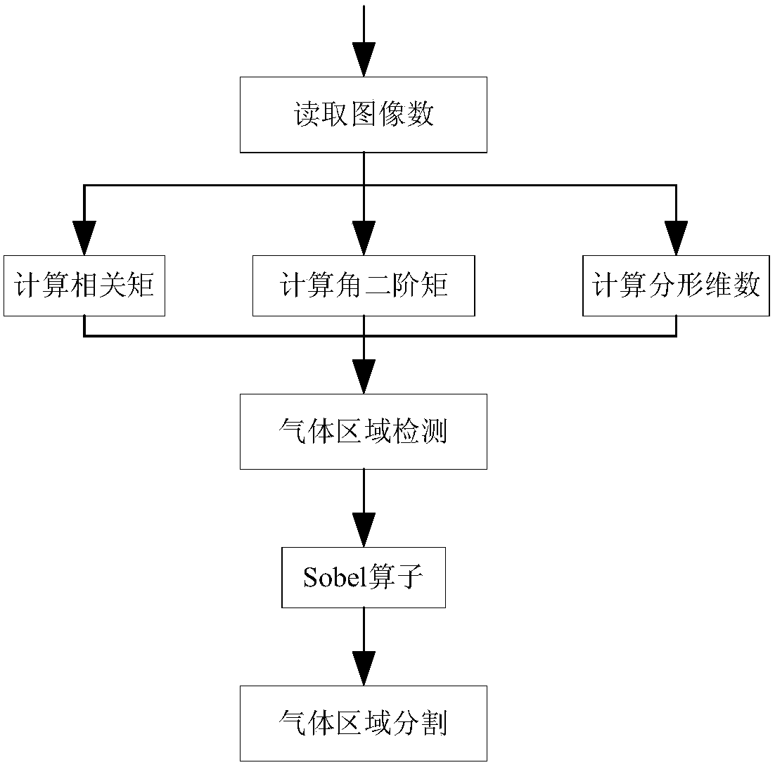
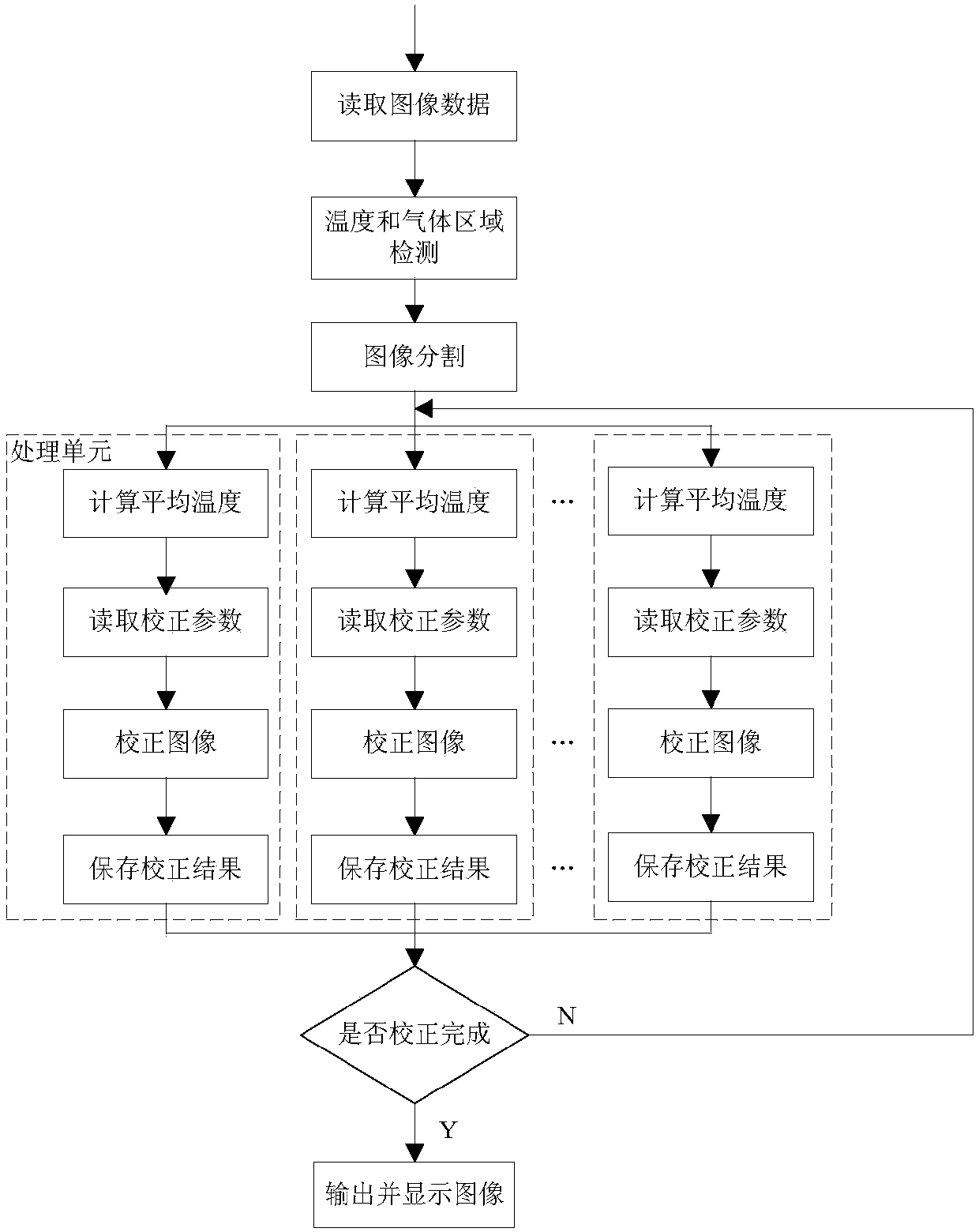
The invention relates to the technical field of data identification, in particular to a non-uniformity correction method for gas leakage detection. The non-uniformity correction method comprises the following steps: a gas leakage detection device acquires a gain coefficient Gij and a bias coefficient Qij of each temperature section and stores acquired infrared images; gas areas in the infrared images are identified through texture and edge features; the temperature of each point of images in non-gas areas is detected, and the areas are divided; non-uniformity correction is performed on images in each sub-area through a non-uniformity correction unit. The invention further provides the gas leakage detection device. The gas leakage detection device comprises a casing, wherein a main control chip is arranged in the casing and connected with an infrared imaging module, a display module and a power module, the power module supplies power to the other modules, and the infrared imaging module comprises an infrared lens, an infrared window and an infrared image sensor which are arranged sequentially. The non-uniformity correction method for gas leakage detection and the gas leakage detection device can improve the gas non-uniformity correction effect and improve the gas leakage detection precision.

Description

technical field [0001] The invention relates to the technical field of data identification, in particular to a non-uniform correction method for gas leakage detection and a gas leakage detection device. Background technique [0002] Thermal imaging cameras are increasingly being used in military, industrial and civilian applications. However, since the response parameters (including responsivity factor and cutoff factor) of each infrared photosensitive element are not the same, even when the input of the infrared focal plane array is uniform, the output voltages of each photosensitive element are also different, thus Non-uniformity problems arise. In addition, the readout circuit and the coupling of the readout circuit to the detector can also cause non-uniformity problems. Therefore, non-uniformity correction is a key problem that needs to be solved in the design of thermal imaging cameras. [0003] Commonly used non-uniformity correction methods include: temperature cal...

Claims


Application Information

Patent Timeline
Patent Type & Authority Patents(China)
IPC IPC(8): G01M3/04
CPCG01M3/04
Inventor 杨裕云吴兴华董玉海李全明王继龙李钊王刚李钢李战丽韩毅
Owner CHINA SAFETY TECH OPTOELECTRONICS CO LTD SHANDONG
Learn More