Loop resistance test method for two-terminal-grounding circuit breaker
A technology of loop resistance and testing method, applied in circuit breaker testing, measuring resistance/reactance/impedance, instruments, etc., can solve problems such as no technical solutions, and achieve the effect of simple operation and simple structure
- Summary
- Abstract
- Description
- Claims
- Application Information
AI Technical Summary
Problems solved by technology
Method used
Image

Examples
Embodiment 1
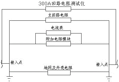
[0043] Embodiment 1: A method for testing the loop resistance of a double-terminal grounding circuit breaker:
[0044] 1) Set the access point between the main circuit resistance and the ground wire and the shell resistance;
[0045] 2) An additional resistance module is set inside the access point, and an ammeter is set on the additional resistance module;
[0046] 3) Add an ammeter outside the main circuit resistance, ground wire and shell resistance and the additional resistance module, and set a total ammeter on both sides of the access point;
[0047] 4) The additional resistance module used is an adjustment resistance unit, and a 300A loop resistance tester is set between the access points.
[0048] 5) The resistance R of the main circuit 1 , current I 1 and standard resistor R 2 , current I 2 And ground grid and shell resistance R 3 , current I 3 The relationship between is satisfied, and the main loop resistance R 1 Less than or equal to 100μΩ, the ground and c...
Embodiment 2
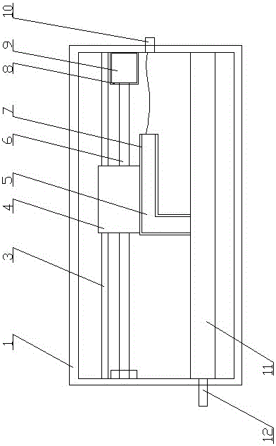
[0053] Embodiment 2: The adjusting resistance unit includes a housing 1, a resistance unit 11 arranged inside the housing 1 and a terminal post 12 arranged outside, a conductive adjustment piece 5 is arranged on the upper part of the resistance unit 11, and a conductive adjustment sheet 5 is arranged on the conductive The lead post 10 at the rear of the adjustment sheet 5, the conductive adjustment sheet 5 adjusts the contact position of the conductive adjustment sheet 5 at the resistance unit 11 through a resistance adjustment member.
[0054] The inside of the housing 1 is a vacuum layer.
[0055] The resistance adjustment member includes a drive motor 9 , a lead screw 6 and an insulating support block 4 connected to the conductive adjustment sheet 5 .
[0056] A metal shield 8 is arranged outside the drive motor 9 .
[0057] The conductive adjusting piece 5 is in the shape of "┌", the outer surface of the conductive adjusting piece 5 is provided with an insulating coating ...
Embodiment 3
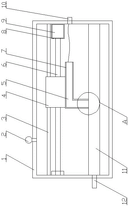
[0058] Embodiment 3: The adjusting resistance unit includes a housing 1, a resistance unit 11 arranged inside the housing 1 and a terminal post 12 arranged outside, a conductive adjustment piece 5 is arranged on the upper part of the resistance unit 11, and a conductive adjustment sheet 5 is arranged on the conductive The lead post 10 at the rear of the adjustment sheet 5, the conductive adjustment sheet 5 adjusts the contact position of the conductive adjustment sheet 5 at the resistance unit 11 through a resistance adjustment member.
[0059] The inside of the housing 1 is a vacuum layer.
[0060] The resistance adjustment member includes a drive motor 9 , a lead screw 6 and an insulating support block 4 connected to the conductive adjustment sheet 5 .
[0061] A metal shield 8 is arranged outside the drive motor 9 .
[0062] The conductive adjusting piece 5 is in the shape of "┌", the outer surface of the conductive adjusting piece 5 is provided with an insulating coating ...
PUM
 Abstract
Description
Claims
Application Information
 - R&D
- Intellectual Property
- Life Sciences
- Materials
- Tech Scout
- Unparalleled Data Quality
- Higher Quality Content
- 60% Fewer Hallucinations
Browse by: Latest US Patents, China's latest patents, Technical Efficacy Thesaurus, Application Domain, Technology Topic, Popular Technical Reports.
© 2025 PatSnap. All rights reserved.Legal|Privacy policy|Modern Slavery Act Transparency Statement|Sitemap|About US| Contact US: help@patsnap.com