Control method of controllable detachable power equipment based on brushless motor

A brushless motor and power equipment technology, applied in the direction of electrical program control, electric components, mechanical energy control, etc., can solve the problems of fixed output power range, non-replaceable motor, and power equipment that cannot reach the operating parameters, etc.

Pending Publication Date: 2016-08-17
ZHEJIANG MINGLEI TOOLS IND
View PDF11 Cites 1 Cited by
  • Summary
  • Abstract
  • Description
  • Claims
  • Application Information

AI Technical Summary

Problems solved by technology

The power equipment generally has a built-in motor, but the existing power equipment is generally equipped with a brush motor, and the power of the brush motor is fixed. At the same time, as an important part of the power equipment, the power equipment of the fixed tool The motor is non-replaceable and the existing power equipment has a built-in brush motor, which leads to a fixed range of output power. Since different tools require power equipment to provide different output power during operation, it cannot satisfy multiple tools using the same power equipment. conditions of
At the same time, most of the existing power equipment can only meet the requirements of providing power for tools. In the current industrial production with a high level of automation, the existing power equipment cannot meet the requirements of controllable operating parameters.

Method used


Image

  • Control method of controllable detachable power equipment based on brushless motor
  • Control method of controllable detachable power equipment based on brushless motor

Examples


Embodiment Construction

[0019] The following are specific embodiments of the present invention and in conjunction with the accompanying drawings, the technical solutions of the present invention are further described, but the present invention is not limited to these embodiments.

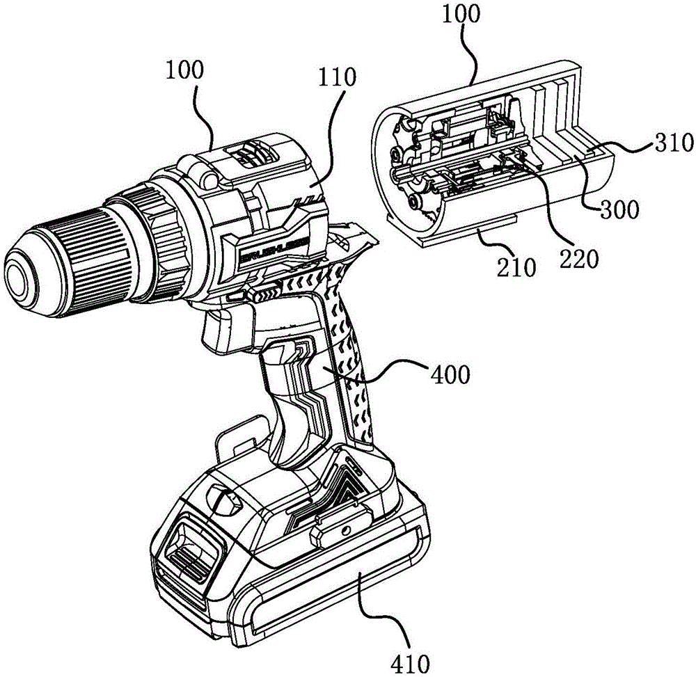
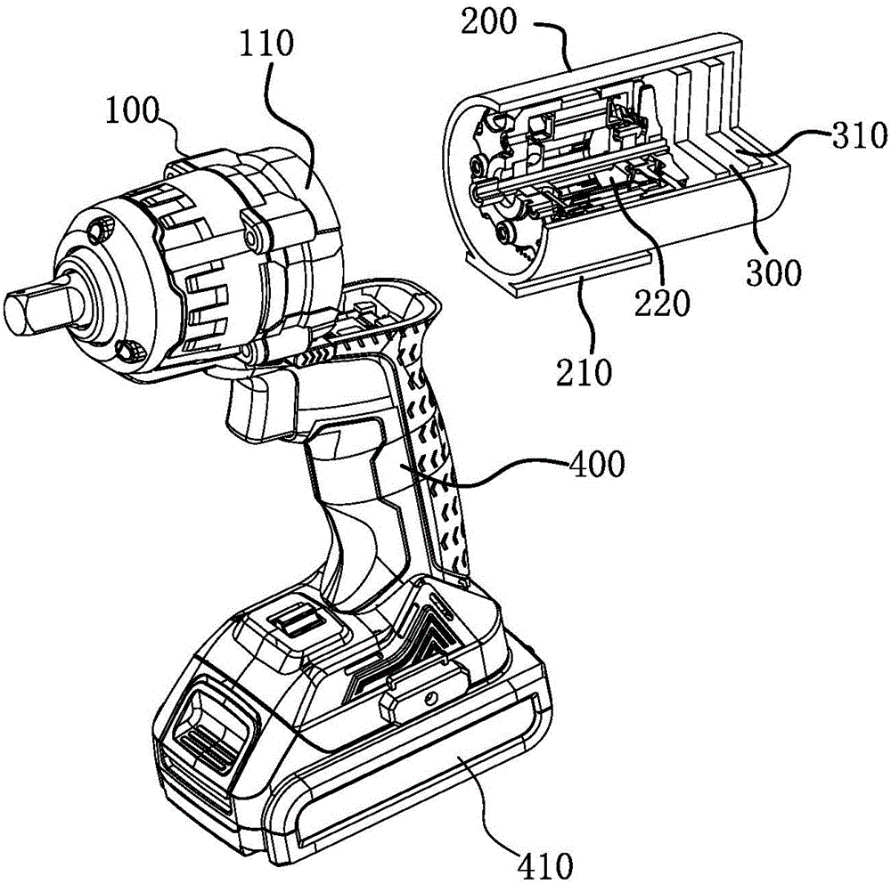
[0020] The present invention discloses a control method of a controllable and detachable power equipment based on a brushless motor 220, including a body module 100, a power module 200 and a switch module 400, and the power module 200 is detachably mounted to the body module 100; The power module 200 includes a brushless motor 220, and a control module 300 for controlling the movement of the brushless motor 220, the control module 300 includes a communication module 320, and the control method includes the following steps:

[0021] S1: using the switch module 400 as a fixed end, install the power module 200 to the switch module 400;

[0022] S2: According to the needs of power equipment, the control module adjusts the outp...


PUM


Abstract

The invention provides a control method of controllable detachable power equipment based on a brushless motor, and belongs to the technical field of power equipment control. The power equipment disclosed by the invention comprises a body module, a power module and a switch module, wherein the power module is detachably installed to the body module; and the power module comprises the brushless motor and a control module used for controlling movement of the brushless motor, and the control module comprises a communication module. The control method comprises the following steps: first of all, the switch module is taken as a fixation end, and the power module is installed to the switch module; secondly, according to needs of the power equipment, the control module regulates operation parameters of the brushless motor in the power module; and then, the control module is started, communication connection between the communication module in the control module and other external equipment is established, and after the communication connection is established, the power equipment can be controlled through the external equipment. The control method disclosed by the invention has the advantages of high efficiency, great convenience and diversified communication modes.

Description

technical field [0001] The invention belongs to the technical field of power equipment control, and relates to a control method for a controllable and detachable power equipment based on a brushless motor. Background technique [0002] In today's industrial production, power equipment is widely used. Many tools involved in industrial production need machines to provide power, so they all need to be equipped with power equipment, and power equipment has become the most indispensable equipment in production. The power equipment generally has a built-in motor, but the existing power equipment is generally equipped with a brush motor, and the power of the brush motor is fixed. At the same time, as an important part of the power equipment, the power equipment of the fixed tool The motor is non-replaceable and the existing power equipment has a built-in brush motor, which leads to a fixed range of output power. Since different tools require power equipment to provide different out...

Claims


Application Information

Patent Timeline
Patent Type & Authority Applications(China)
IPC IPC(8): G05B19/04B25F5/00
CPCB25F5/00G05B19/04B23B45/02H02K7/14
Inventor 翁磊
Owner ZHEJIANG MINGLEI TOOLS IND
Why Eureka
Try Eureka