
Temperature and humidity controller

A controller, temperature and humidity technology, used in non-electric variable control, control/regulation systems, and simultaneous control of multiple variables. The effect of good anti-condensation effect, intuitive interface and high reliability

Inactive Publication Date: 2016-08-17
NANTONG FANGDU ESTATE CO LTD
View PDF4 Cites 4 Cited by
  • Summary
  • Abstract
  • Description
  • Claims
  • Application Information

AI Technical Summary

Problems solved by technology

The commonly used method is to use a resistive condensation sheet as a sensor, and use the inflection point of the parameter curve of this condensation sheet to realize the purpose of controlling the heater to start. Although this method has a simple circuit, its accuracy is very poor, and condensation has often occurred. However, the controller has not started the heater, and the setting of the starting control point cannot be changed. Due to the vast territory of our country and the different climates, the temperature in each region
The temperature difference is very large, so the control requirements are also different, and this kind of controller cannot meet the better use requirements.

Method used


Image

  • Temperature and humidity controller

Examples


Embodiment Construction

[0008] In order to further explain the technical means and effects adopted by the present invention to achieve the intended invention purpose, the specific implementation, structure, features and effects of the present invention will be described in detail below in conjunction with the accompanying drawings and preferred embodiments.

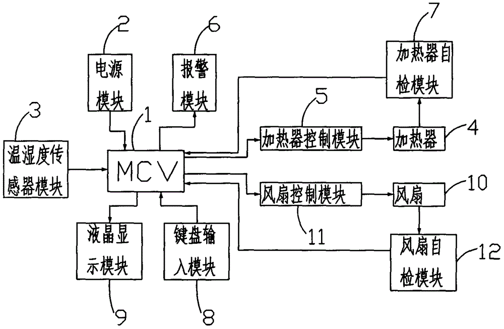
[0009] see figure 1 As shown, a temperature and humidity controller 100 is connected with a power supply module 2, a temperature and humidity sensor module 3, an alarm module 6, a keyboard input module 8 and a liquid crystal display module 9 on the MCU microcontroller 1, and the heater control module 5 is respectively It is connected with the MCU microcontroller 1 and the heater 4, the heater 4 is connected with the heater self-check module 7, and the heater self-check module 7 is connected with the MCU microcontroller 1. The fan control module 11 is respectively connected with the MCU microcontroller 1 and the fan 10 , the fan 10 is connected w...


PUM


Abstract

A temperature and humidity controller comprises an MCU (microprogrammed control unit), a power module, a temperature and humidity sensor module, an alarm module, a keyboard input module, a liquid crystal display module, a heater control module, a heater, a fan control module and a fan, wherein the power module, the temperature and humidity sensor module, the alarm module, the keyboard input module and the liquid crystal display module are connected onto the MCU; the heater control module is connected with the MCU and the heater; the fan control module is connected with the MCU and the fan.

Description

technical field [0001] The invention relates to a temperature controller, in particular to a humidity controller used in switch cabinets, central cabinets, box-type substations and other equipment in the power system. Background technique [0002] In order to ensure the normal and reliable operation of high-voltage power equipment such as switch cabinets and central cabinets, there are high requirements for anti-condensation inside them. At present, in order to prevent condensation inside the equipment, one or two heaters will be installed to use the heat generated during work to increase the temperature and prevent condensation. Due to the high power consumption of the heater, in consideration of energy saving, the heater It is best to work only when needed, and there are many ways to control the heater. The commonly used method is to use a resistive condensation sheet as a sensor, and use the inflection point of the parameter curve of this condensation sheet to realize th...

Claims


Application Information

Patent Timeline
Patent Type & Authority Applications(China)
IPC IPC(8): G05D27/02
CPCG05D27/02
Inventor 王国斌
Owner NANTONG FANGDU ESTATE CO LTD
Learn More