Intelligent imaging apparatus with cup receiving function and all-directionally adjustable view angle

An imaging device, a full-view technology, applied in mechanical equipment, instruments, electrical digital data processing, etc., can solve problems such as obstruction, the display screen cannot share communication, and people cannot adjust the height or angle of the display screen.

Inactive Publication Date: 2016-08-17
CHENGDU ZHIRENSHANYONG INFORMATION TECH CO LTD
View PDF0 Cites 3 Cited by
  • Summary
  • Abstract
  • Description
  • Claims
  • Application Information

AI Technical Summary

Problems solved by technology

Existing imaging devices such as computer monitors often cannot adjust the height or angle of the display screen, and some can only adjust the height
We are monitoring or in the office, and sometimes we need to communicate with colleagues, but the display cannot

Method used


Image

  • Intelligent imaging apparatus with cup receiving function and all-directionally adjustable view angle
  • Intelligent imaging apparatus with cup receiving function and all-directionally adjustable view angle
  • Intelligent imaging apparatus with cup receiving function and all-directionally adjustable view angle

Examples


Embodiment 1

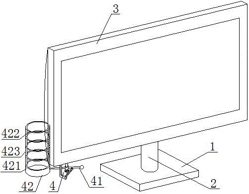
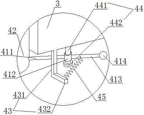
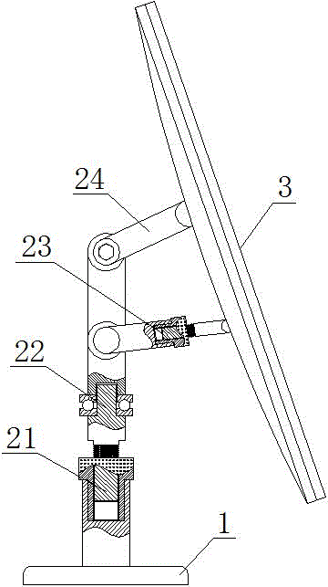
[0028] A high-efficiency heat-dissipating intelligent imaging device that can accommodate water cups and adjust the full viewing angle, including a base 1, a bracket 2, and a display screen 3, and is characterized in that a water cup storage mechanism 4 is provided at one end of the bottom of the display screen 3. Mechanism 4 comprises turret 41, water cup holder 42, limit frame 43, fixed head 44, spring 45; Said fixed head 44 comprises center rod 441 and positioning head 442, and one end of said center rod 441 is fixed on the bottom of display screen 3 The other end of the central rod 441 is fixedly connected with the positioning head 442; the turret 41 includes a cup holder rod 411, a rotating head 412, a pull rod 413, and a pull rod head 414 connected in sequence. The cup holder rod 411 One end of the cup holder is fixedly connected to the cup holder 42, and the other end of the cup holder rod 411 is connected to the rotating head 412, which is a hollow cylindrical structure...

Embodiment 2

[0032] On the basis of the first embodiment, the rotating frame 41 and the limit frame 43 are arranged at the same end of the bottom of the display screen 3, which can make the operation more convenient. The vertical section 431 of the spacer is connected to the front position of the end of the bottom surface of the display screen 3, and the central rod 441 of the fixed head 44 is arranged at the rear position of the end of the bottom surface of the display screen 3, so that the axis of the spring 45 is aligned with the turret. 41 has a larger included angle, which increases the arm of force and facilitates the pulling rod head 414 to be moved.

Embodiment 3

[0034] On the basis of the above-mentioned embodiments, the inner surface of the rotating head 412 is pasted with a protection pad, and the surface of the protection pad is coated with lubricant. This makes the dialing of the rotating device more flexible, and is convenient for taking and placing the water cup.


PUM


Abstract

The invention relates to the field of intelligent imaging equipment, in particular to an intelligent imaging apparatus with cup receiving function and all-directionally adjustable view angle, and aims to provide an intelligent imaging apparatus with a cup receiving mechanism and optionally adjustable display screen height, rotational angle and tilting angle. According to a technical scheme of the invention, the intelligent imaging apparatus with cup receiving function and all-directionally adjustable view angle comprises a base, a support and a display screen, the cup receiving mechanism is disposed at one end of the bottom of the display screen and comprises a rotary frame, a cup holder, a limiter, a fixing head and a spring, the support comprises a telescoping mechanism, a rotating mechanism, an angle control mechanism and a fixing rod. The invention is applicable to intelligent imaging equipment with cup receiving function and all-directionally adjustable view angle.

Description

Technical field [0001] The invention involves the field of intelligent imaging equipment, especially a smart imaging device that can be reinforced with a reinforcement cup and a comprehensive adjustment perspective. Background technique [0002] Imaging equipment is usually called monitor, belonging to I / O devices, that is, input and output device.It is a display tool that displays certain electronic files through specific transmission devices to the screen and then reflects the human eye.According to the different manufacturing materials, it can be divided into: cathode ray tube display (CRT), plasma display PDP, LCD display LCD, and so on.In a broad sense, large screens, televisions, BSV LCD splicing fluorescent screens, mobile phones and fast translations can be regarded as imaging equipment.It is very widely used. It is as large as satellite monitoring. It can be said that in modern society, its figure is everywhere. Its structure is generally a round base and fuselage.There ...

Claims


Application Information

Patent Timeline
IPC IPC(8): G06F1/16F16M11/06F16M11/28
CPCG06F1/1601F16M11/06F16M11/28G06F1/1607G06F2200/1613
Inventor 张凯胜刘华吴小莉
Owner CHENGDU ZHIRENSHANYONG INFORMATION TECH CO LTD
Why Eureka
Try Eureka