Current transformer device capable of being installed fast in electrified mode

A technology of current transformers and transformers, applied in the direction of inductors, transformers/reactors installation/support/suspension, circuits, etc., can solve the problems of easy danger, low efficiency, inconvenience, etc., and achieve the convenience of live switching process Effect

Active Publication Date: 2016-08-17
STATE GRID CORP OF CHINA +2
View PDF9 Cites 2 Cited by
  • Summary
  • Abstract
  • Description
  • Claims
  • Application Information

AI Technical Summary

Problems solved by technology

[0003] In the process of using the existing open-type current transformer on the switch on the pole, it is often necessary to put the current transformer on the cable under test to realize the purpose of the cable passing through the current transformer, because the cable will be relatively long in general , so most of the time, the current transformer is disassembled into two semicircles, and then the cable is placed in the center of the two semicircles, and then the current transformer is reassembled into a circle, so as to achieve the current The transformer is fixed to the cable under test, and the existing current transformer is disassembled and connected by bolts. Therefore, in the process of live replacement of the current transformer, a screwdriver is needed, which is very inconvenient. , at the same time, the diameter of the inner circle of the current transformer is generally much larger than the diameter of the cable, so there will be a large gap between the current transformer and the cable, so that the current transformer cannot be well fixed on the cable under test, and because the cable Generally, they are installed in higher places. Therefore, the existing manual installation method requires people to climb to a high place for manual installation. Firstly, the efficiency is low, and secondly, dangerous situations are prone to occur during live installation.

Method used


Image

  • Current transformer device capable of being installed fast in electrified mode
  • Current transformer device capable of being installed fast in electrified mode
  • Current transformer device capable of being installed fast in electrified mode

Examples


Embodiment Construction

[0017] The present invention will be described in further detail below in conjunction with the embodiments given in the accompanying drawings.

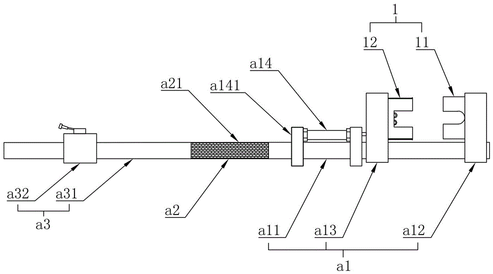
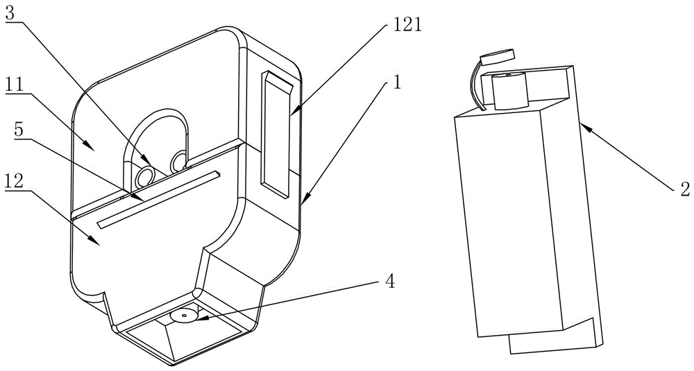
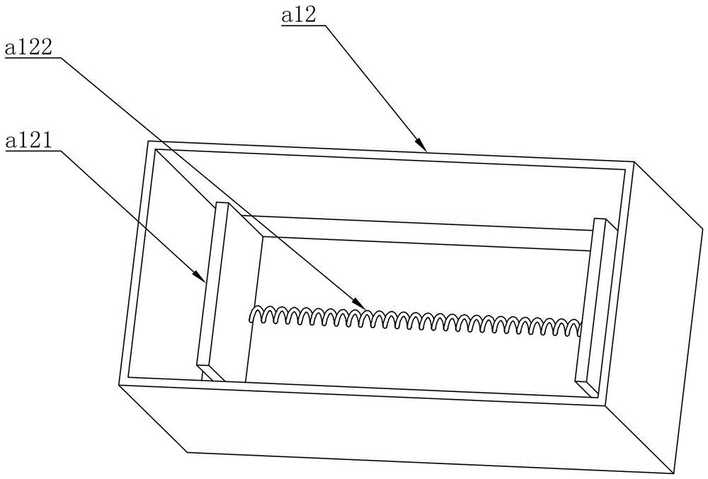
[0018] refer to Figures 1 to 5 As shown in the present embodiment, a current transformer device that can be quickly installed with electricity includes a transformer bracket a and a transformer. The transformer bracket includes a mechanical part a1, an insulating part a2 and an operating part a3. The mechanical part a1 includes a first connecting rod a11 and an upper mold a12 and a lower mold a13 both sleeved on the first connecting rod a11, the upper mold a12 is fixed on the top of the first connecting rod a11, and the lower mold a13 The lower part of the a12 slides up and down, and the lower part of the lower mold a13 is provided with a cylinder a14, and both ends of the cylinder body of the cylinder a14 are fixedly connected with a fixed piece a141, and the fixed piece a141 is sleeved on the first connecting rod a11 Above, the pu...


PUM


Abstract

The invention discloses a current transformer device capable of being installed fast in an electrified mode. The current transformer device comprises a transformer bracket and a transformer. The transformer bracket comprises a mechanical part, an insulating part and an operation part. The mechanical part comprises a first connecting rod, an upper die and a lower die, wherein the first connecting rod is sleeved with the upper die and the lower die. The transformer comprises an induction body inducting with an external cable and a measuring body for measuring the induction current value. The inducting body and the measuring body are connected through a wire. The inducting body comprises a first shell, a second shell capable of being detachably connected with the first shell, and a winding arranged in the first shell and the second shell. According to the current transformer device capable of being installed fast in the electrified mode, the first shell and the second shell are arranged on the transformer, the mechanical part, the insulating part and the operation part are arranged, and therefore the current transformer can be installed fast and effectively in the electrified mode.

Description

technical field [0001] The invention relates to a current transformer, in particular to a current transformer device that can be quickly charged and installed. Background technique [0002] The structure of the open-type current transformer does not have a primary winding, and the current-carrying (load current) cable passes through a circular (or other shape) iron core made of silicon steel sheets to act as the primary winding, and the secondary winding is directly and evenly distributed. Wound on a circular iron core, it is connected in series with the secondary load of current coils such as instruments, relays, and transmitters to form a closed loop, so as to achieve the purpose of measuring the cable load current. [0003] In the process of using the existing open-type current transformer on the switch on the pole, it is often necessary to put the current transformer on the cable under test to realize the purpose of the cable passing through the current transformer, beca...

Claims


Application Information

Patent Timeline
Patent Type & Authority Applications(China)
IPC IPC(8): H01F27/06H01F38/30
CPCH01F27/06H01F38/30
Inventor 戴瑞海郑贤舜夏陈喆郑晟金海晨夏惠惠斯捷南隆梁一晨周波庞京海林伟恺钱康柴谦益郑文斌王化陈宜李泾陈坚黄首孟陈发棋黄良俊林振兴陈怡
Owner STATE GRID CORP OF CHINA
Why Eureka
Try Eureka