

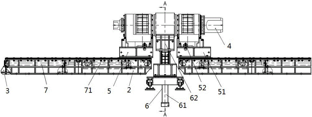
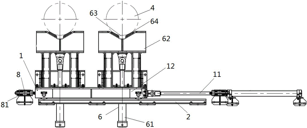
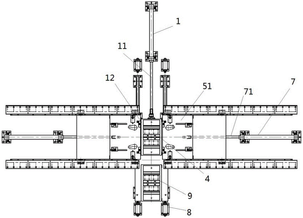
Double-station universal type hydraulic automatic roller detaching equipment
A general-purpose, double-station technology, applied to metal processing equipment, manufacturing tools, metal rolling, etc., can solve the problems of difficult assembly, low frequency of roll change, large initial investment, etc., and achieve safe disassembly and installation, and extended The effect of improving the service life and improving the efficiency of disassembly and assembly
- Summary
- Abstract
- Description
- Claims
- Application Information
AI Technical Summary
Problems solved by technology
Method used
Image

Examples
Embodiment Construction
[0030] It should be noted that, in the case of no conflict, the embodiments of the present invention and the features in the embodiments can be combined with each other.
[0031] In describing the present invention, it should be understood that the terms "center", "longitudinal", "transverse", "upper", "lower", "front", "rear", "left", "right", The orientations or positional relationships indicated by "vertical", "horizontal", "top", "bottom", "inner", "outer", etc. are based on the orientation or positional relationships shown in the drawings, and are only for the convenience of describing the present invention Creation and simplification of description, rather than indicating or implying that the device or element referred to must have a specific orientation, be constructed and operate in a specific orientation, and therefore should not be construed as limiting the invention. In addition, the terms "first", "second", etc. are used for descriptive purposes only, and should no...
PUM
 Abstract
Description
Claims
Application Information