A chain ditch scarifier

A ripper and chain technology, which is applied in the fields of soil preparation machinery, agricultural machinery and implements, shovels, etc., can solve the problems of no automatic trencher and large labor input, and achieve high work efficiency, reduced investment, and depth control. Effect

Active Publication Date: 2018-01-19
BAODING ZHONGSEN MACHINERY MFG CO LTD
View PDF4 Cites 0 Cited by
  • Summary
  • Abstract
  • Description
  • Claims
  • Application Information

AI Technical Summary

Problems solved by technology

[0004] The purpose of the present invention is to provide a chain type ditch scarifier to solve the problem of large labor input in the early stage of yam planting and no automatic ditching machine

Method used


Image

  • A chain ditch scarifier
  • A chain ditch scarifier
  • A chain ditch scarifier

Examples


Embodiment Construction

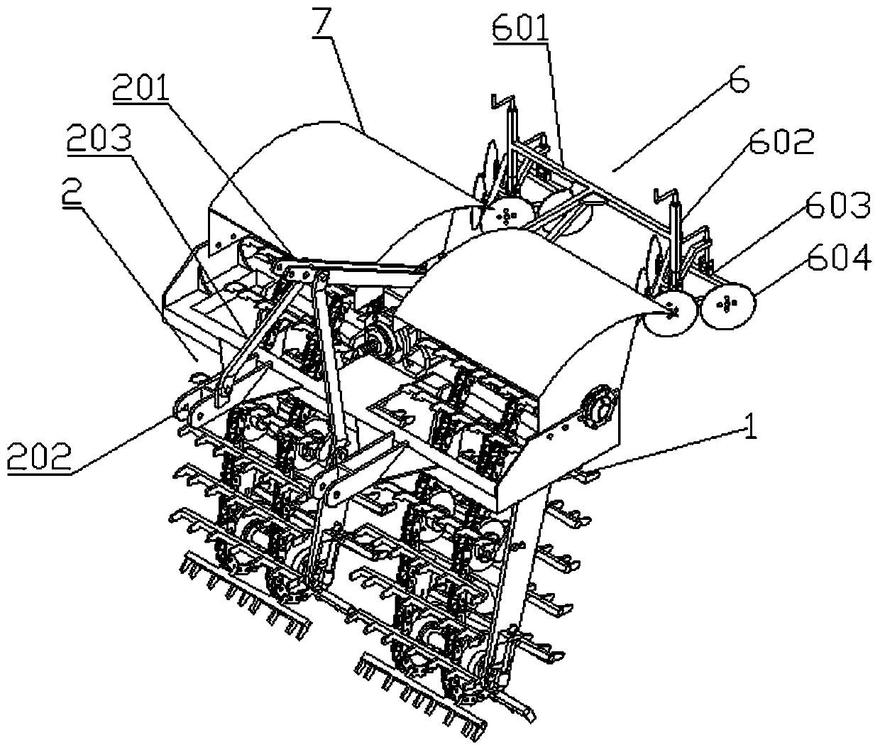
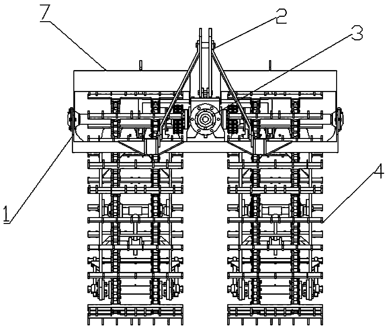
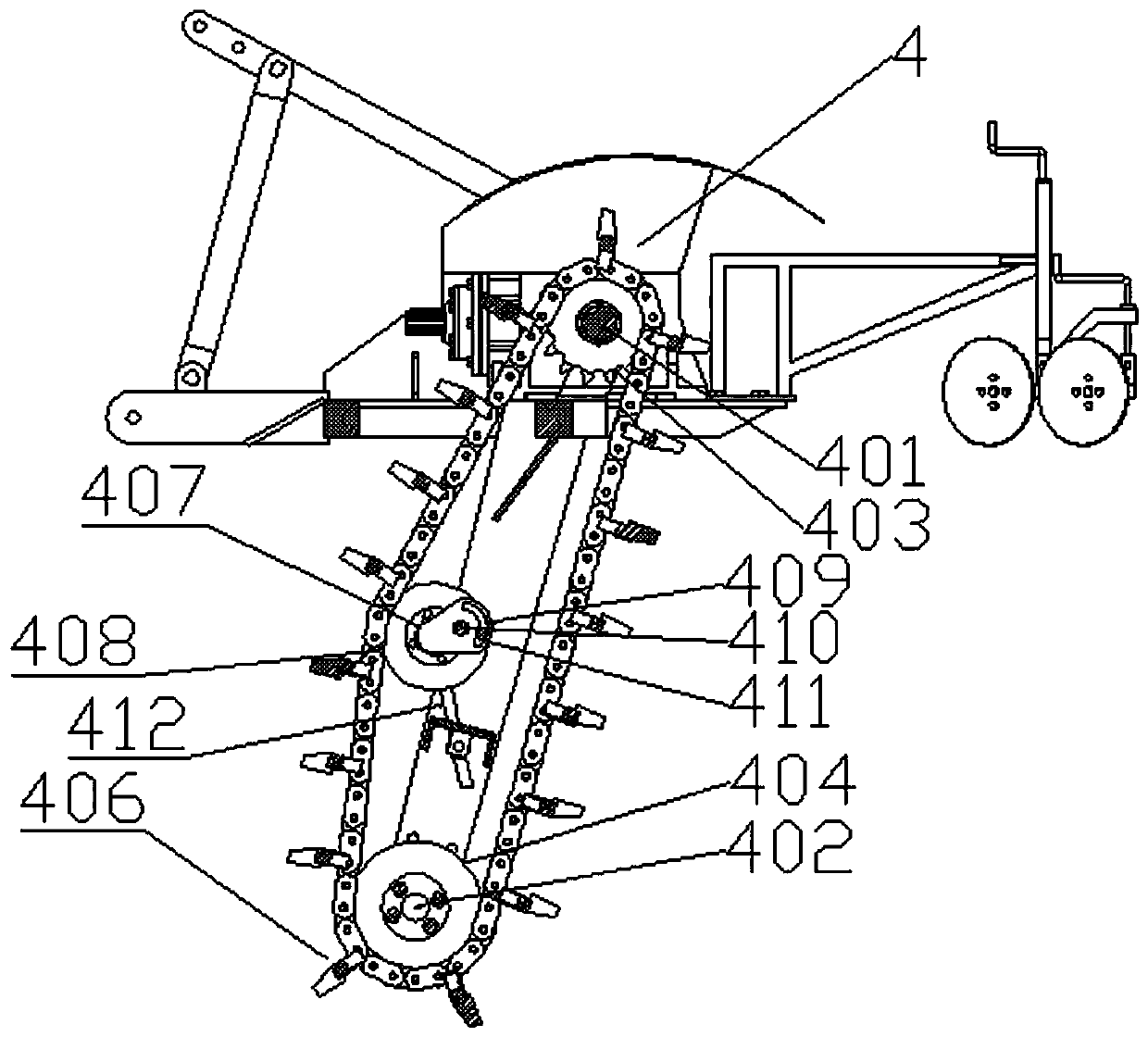
[0031] Such as Figure 1-5 As shown, a chain type ditching scarifier includes: a frame 1, the frame 1 is movably connected with a locomotive through a connecting frame 2, and the chain type ditching scarifier is moved forward by the traction of the locomotive;

[0032] Fixed on the frame 1, with the reduction box 3 of the engine power transmission of the locomotive, the torque is increased, and the output power of the ditching and loosening device is improved;

[0033] The ditching and loosening device 4 is arranged on the frame 1 and connected with the power output shaft of the reduction box 3; the ditching and loosening device 4 includes a The driving shaft 401 and the driven shaft 402; the driving shaft 401 is located at the upper end of the frame 1, and the driving shaft 401 is provided with two sprockets 403 at intervals; the driven shaft 402 is located at the lower end of the frame 1 , and the driven shaft 402 is provided with two guide wheels 404 at intervals; the two ...


PUM


Abstract

The invention discloses a chained ditching loosener which comprises a rack, a connecting rack, a gearbox and a ditching loosening device. The ditching loosening device comprises a driving shaft and a driven shaft which are rotationally erected on the rack; two chain wheels are arranged on the driving shaft at an interval in a sleeving manner; two guide wheels are arranged on the driven shaft at an interval in a sleeving manner; the two chain wheels and the two guide wheels respectively correspond to one another on a longitudinal surface; annular chains are arranged on two groups of chain wheels and guide wheels which respectively correspond to one another; the driving shaft is in transmission connection with a power output shaft of the gearbox; a plurality of ditching loosening cutters are arranged between the two annular chains. According to the chained ditching loosener disclosed by the invention, the rack is connected to a locomotive by virtue of the connecting rack so as to obtain traction force; meanwhile, large-torque rotating force is obtained to drive the ditching loosening device by virtue of the gearbox, and automatic ditching loosening of the land is realized; and moreover, the ditching width is reasonable, the depth is controllable, the working efficiency is high, and the input of labor force is greatly reduced.

Description

technical field [0001] The invention relates to the field of agricultural machinery, in particular to a chain type ditch scarifier. Background technique [0002] At present, domestic yam planting labor is very large. Since the growth characteristic of yam is downward growth, the mature yam can grow downwards between 1m and 2m. Natural growth force, it is difficult to penetrate to such depths. So people in the planting process, usually land is turned over, because its depth of turning over is big, so wasted a large amount of labor force, has influenced the plantation of hemp yam. [0003] So there is an urgent need for an automatic ditching machine to meet the planting requirements of hemp yam. Contents of the invention [0004] The purpose of the present invention is to provide a chain type ditching and scarifying machine, which solves the problems of large labor input and no automatic ditching machine in the early stage of yam planting. [0005] In order to solve the p...

Claims


Application Information

Patent Timeline
Patent Type & Authority Patents(China)
IPC IPC(8): A01B39/08A01B39/22A01B49/02
CPCA01B39/085A01B39/22A01B49/022
Inventor 梁蕾
Owner BAODING ZHONGSEN MACHINERY MFG CO LTD
Why Eureka
Try Eureka