Movable computer tomography device

A tomographic imaging and computer technology, applied in the field of medical equipment, can solve the problems of uneven transmission, gear climbing, pitch error, etc., and achieve the effect of high transmission precision

Inactive Publication Date: 2016-08-24
SUZHOU INST OF BIOMEDICAL ENG & TECH CHINESE ACADEMY OF SCI
View PDF10 Cites 12 Cited by
  • Summary
  • Abstract
  • Description
  • Claims
  • Application Information

AI Technical Summary

Problems solved by technology

[0002] The rotation of the scanning system of the existing computed tomography device is mostly driven by a synchronous belt. The disadvantage is that the pitch of the teeth of the synchronous belt will change during the manufacturing and force transmission process, resulting in unequal pitches when the synchronous belt meshes with the pulley. Pitch error occurs, and excessive pitch error will make the transmission unstable, resulting in vibration and gear climbing phenomenon; at the same time, the axis position of the scanning system of the existing mobile computer tomography device is fixed, that is, during the scanning process, the axis of the scanning system only It can be kept parallel to the long axis of the scanned object. However, when inspecting the cervical spine and lumbar spine, it is often necessary to adjust the tilt angle of the scanning system according to the physiological curvature of the cervical spine and lumbar spine, so that the planned scanning level can scan the cervical spine that needs to be checked more accurately. and lumbar level
Therefore, the existing mobile computed tomography device with a fixed axial position of the scanning system limits the imaging accuracy of the cervical spine and lumbar spine.

Method used


Image

  • Movable computer tomography device
  • Movable computer tomography device
  • Movable computer tomography device

Examples


Embodiment Construction

[0017] The present invention will be further described in detail below in conjunction with the accompanying drawings, so that those skilled in the art can implement it with reference to the description.

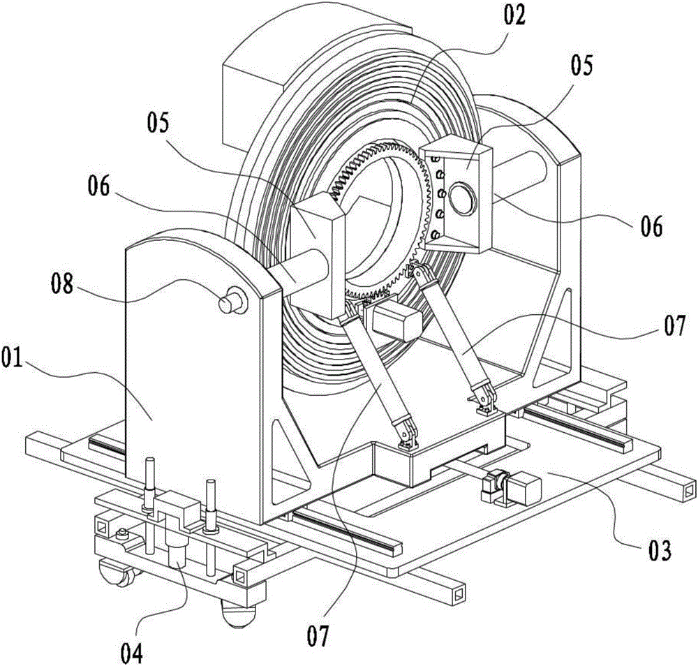
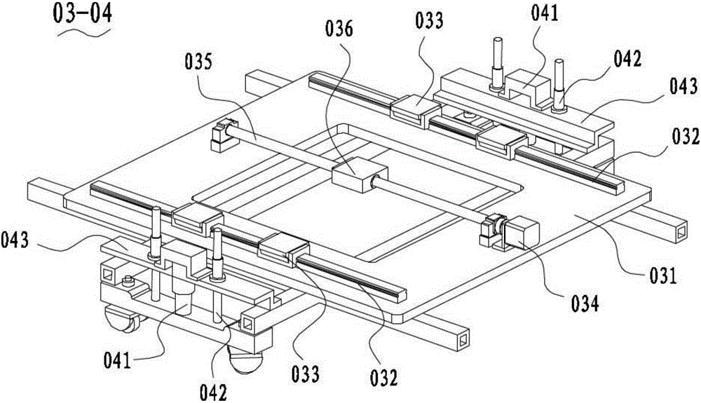
[0018] Such as figure 1 As shown, the present invention provides a mobile computed tomography device, including: a support base 01 , a scanning system 02 , a tilting mechanism, a traverse mechanism 03 and a lifting mechanism 04 .

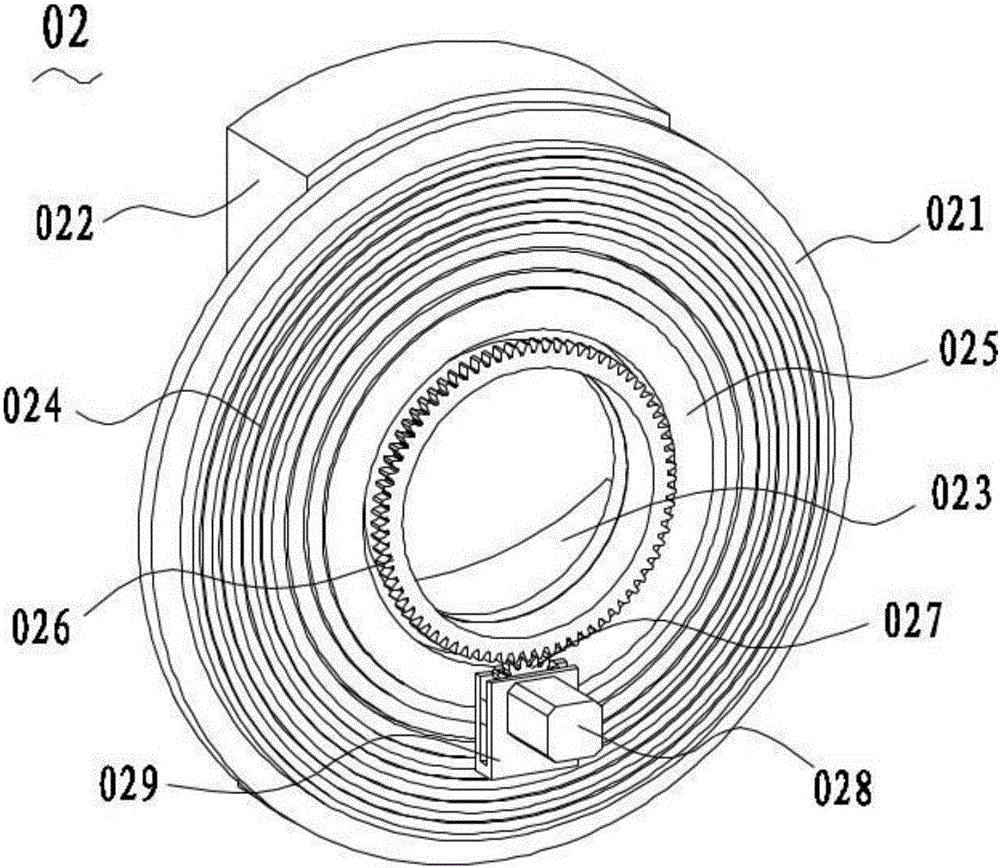
[0019] Such as figure 2 As shown, the scanning system 02 is placed above the support base 01, which includes a turntable 021, a tube 022 and a detector 023 fixed at the rear of the turntable 021, and a slider fixed at the front of the turntable 021. The ring 024 and the driven gear 026, the driving gear 027 cooperating with the driven gear 026, the rotating motor 028 driving the driving gear 027 to rotate, the front part of the turntable 021 is also provided with a bearing 025, and the bearing The outer ring of 025 is fixed on the front part of ...


PUM


Abstract

The invention discloses a mobile computed tomography device, comprising: a support base; a scanning system, which includes a turntable, a ball tube and a detector fixed at the rear of the turntable, a slip ring fixed at the front of the turntable and The driven gear, the driving gear cooperating with the driven gear, the rotating motor that drives the driving gear to rotate, the front part of the turntable is also provided with a bearing; the linear drive, one end of which is hinged on the support seat, The other end of the linear driver is hinged on the inner ring of the bearing; the connecting shaft has a corner block fixed at one end, the corner block is fixed on the inner ring of the bearing, and the other end of the connecting shaft It is pivotally connected to the side of the supporting base, and the other end of the connecting shaft is connected with an encoder. The mobile computed tomography device provided by the invention is safe and reliable, has high transmission precision, and can realize the scanning system to work at a certain inclination angle.

Description

technical field [0001] The invention relates to the technical field of medical devices, in particular to a mobile computed tomography imaging device. Background technique [0002] The rotation of the scanning system of the existing computed tomography device is mostly driven by a synchronous belt. The disadvantage is that the pitch of the teeth of the synchronous belt will change during the manufacturing and force transmission process, resulting in unequal pitches when the synchronous belt meshes with the pulley. Pitch error occurs, and excessive pitch error will make the transmission unstable, resulting in vibration and gear climbing phenomenon; at the same time, the axis position of the scanning system of the existing mobile computer tomography device is fixed, that is, during the scanning process, the axis of the scanning system only It can be kept parallel to the long axis of the scanned object. However, when inspecting the cervical spine and lumbar spine, it is often ne...

Claims


Application Information

Patent Timeline
Patent Type & Authority Applications(China)
IPC IPC(8): A61B6/03A61B6/00
CPCA61B6/03A61B6/44
Inventor 马昌玉范梅生郑健袁刚李铭孙明山郁朋刘兆邦张寅吴中毅陈奭雷恒波
Owner SUZHOU INST OF BIOMEDICAL ENG & TECH CHINESE ACADEMY OF SCI
Why Eureka
Try Eureka