Assembled type minimally invasive lumbar interbody fusion apparatus

An intervertebral fusion device and fusion device technology, applied in the direction of spinal implants, etc., can solve the problems of inability to carry out intervertebral fusion, inability to work catheter implantation in the intervertebral space, etc.

Inactive Publication Date: 2016-08-24
THE FIRST AFFILIATED HOSPITAL OF GUANGZHOU MEDICAL UNIV (GUANGZHOU RESPIRATORY CENT)
View PDF7 Cites 6 Cited by
  • Summary
  • Abstract
  • Description
  • Claims
  • Application Information

AI Technical Summary

Problems solved by technology

[0002] At present, minimally invasive intervertebral fusion mainly deals with the target intervertebral space through a small incision, and implants the intervertebral fusion device filled with bone material into the intervertebral space. Due to the large size of the existing intervertebral fusion device, it is impossible to pass through the intervertebral disc and foramina. Working catheter implanted in intervertebral space
Therefore, although many experts use discoscopy, transforaminal endoscopic spinal canal decompression, and intervertebral disc treatment, it is still impossible to carry out truly minimally invasive intervertebral fusion operations under the microscope and under the tunnel.

Method used


Image

  • Assembled type minimally invasive lumbar interbody fusion apparatus
  • Assembled type minimally invasive lumbar interbody fusion apparatus
  • Assembled type minimally invasive lumbar interbody fusion apparatus

Examples


Embodiment Construction

[0013] In the following, the present invention will be further described in conjunction with the accompanying drawings and specific embodiments, so as to understand the technical ideas claimed in the present invention more clearly.

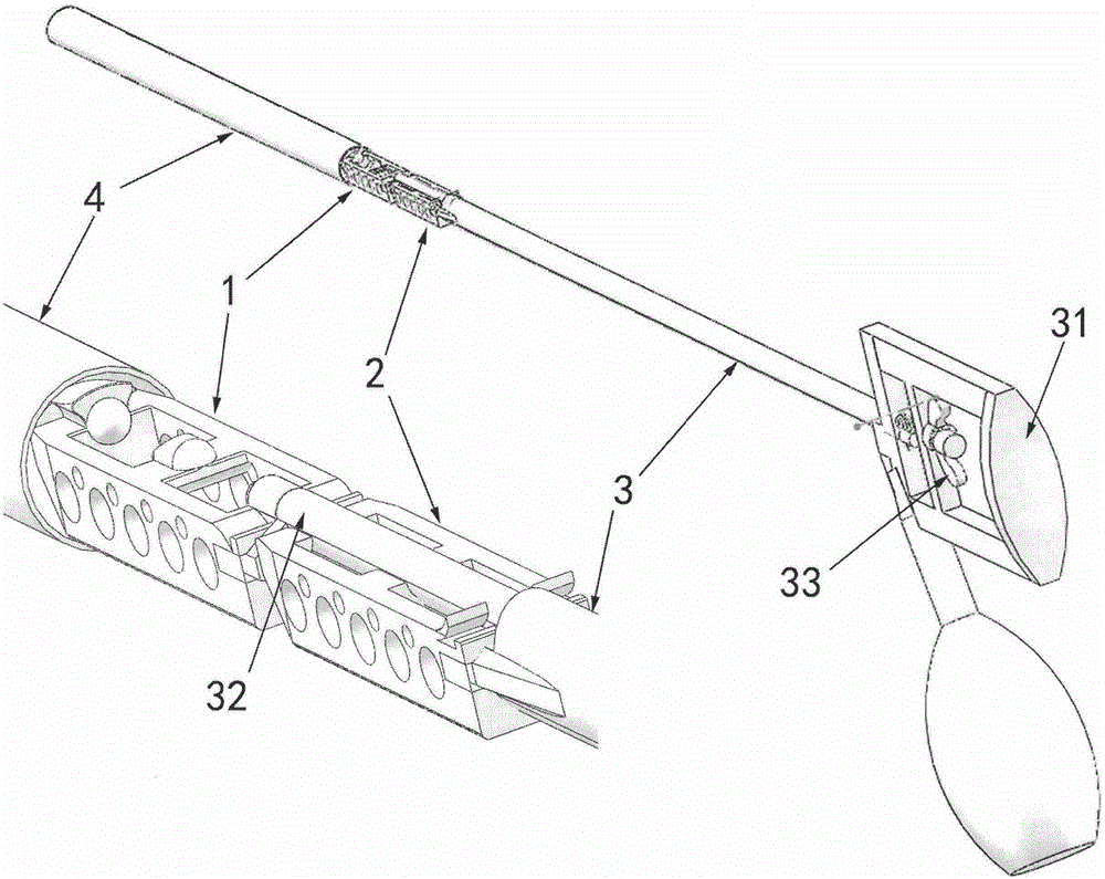
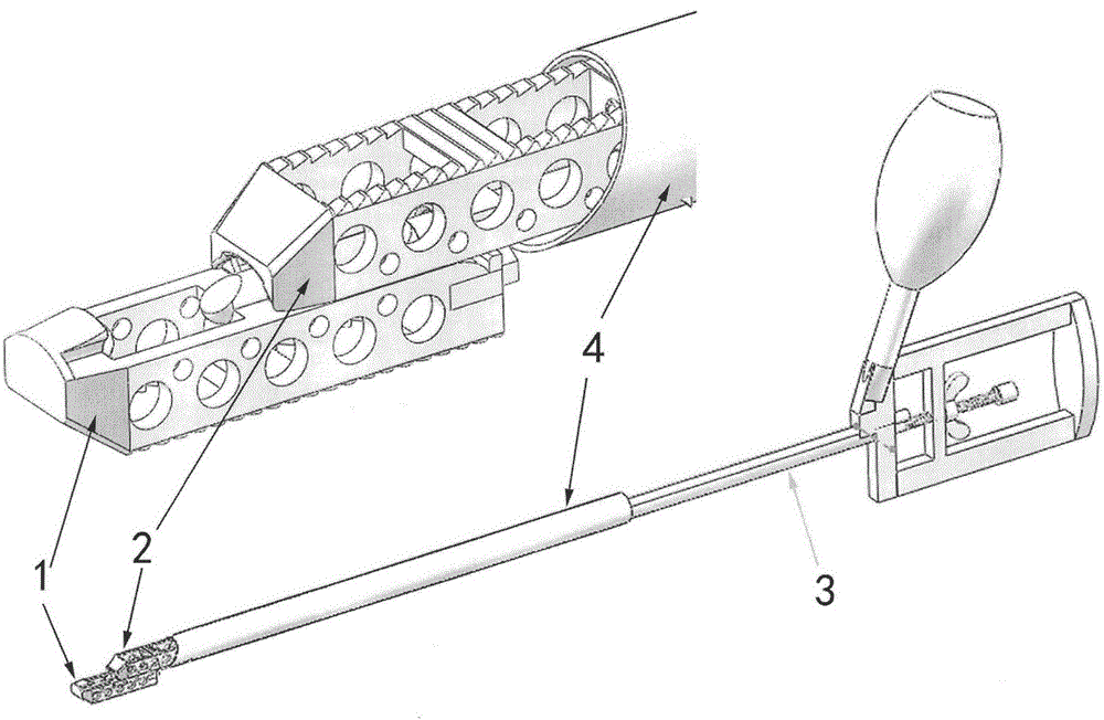
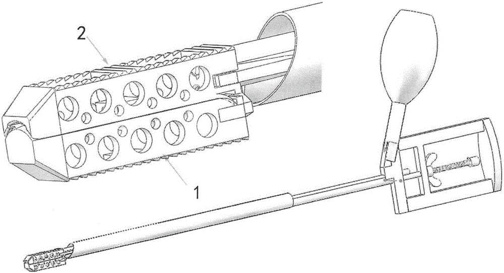
[0014] Such as figure 1 , 2 , 3, it is an assembled minimally invasive intervertebral fusion device of the present invention, including a part A 1 with a dorsal front slot 13, a rear slot 15, a middle guide post 14, and a part A inserted in the A part 1. The back side is provided with the B part 2 of the ventral front card 21, the rear card 23, and the middle guide groove 22; the back side of the front guide part of the A part has a card slot 13 that opens to both sides, and the front end of the card slot has a front stopper 16, so as to be interlocked with the front card 21 of the guide part of the B part, and block the B part from sliding forward; there is a semi-cylindrical segmented guide column 14 in the middle of the back side of the body o...


PUM


Abstract

The invention discloses an assembled minimally invasive intervertebral fusion device for the lumbar spine, which comprises a part A provided with a dorsal front and rear card slot and a middle guide column, and a front and back card inserted in the back side of the A part and provided with a ventral front and back card and a middle guide groove The part B of the fusion device; the part A of the fusion device is composed of a front-end guide part and a rear side body; the back side of the front-end guide part of the part A has a card slot opening to both sides, and the back side of the part A is in the middle of the back side A semi-cylindrical guide column is arranged, and upwardly opening draw-in grooves are arranged on both sides of the rear part of the back side. There are cards on both sides of the ventral side of the front end guide part of the fusion device B, and there is a semi-cylindrical guide groove in the middle of the ventral side of the rear side of the B part, and there are elastic cards on both sides of the ventral rear part. The present invention adopts the split assembly design of two parts of fusion device A and B. During use, the supporting handles can be connected in series to hold the two parts of fusion device A and B, and the working catheter hammer through the intervertebral foramen mirror and the intervertebral disc mirror Into the intervertebral space, when part A enters the intervertebral space and the rear end exits the working sleeve, turn the handle 180 degrees, so that the two parts A and B are hammered into the intervertebral space relative to each other up and down, so as to realize intervertebral disc or intervertebral foramenoscopy. Interfusion.

Description

technical field [0001] The invention relates to a lumbar minimally invasive intervertebral fusion device. Background technique [0002] At present, the minimally invasive intervertebral fusion mainly deals with the target intervertebral space through a small incision, and implants the intervertebral fusion device filled with bone material into the intervertebral space. Due to the large size of the existing intervertebral fusion device, it is impossible to pass through the intervertebral disc or foramina. A working catheter is inserted into the intervertebral space. Therefore, although many experts use discoscopy, intervertebral foraminal decompression of the spinal canal, and intervertebral disc treatment, it is still impossible to carry out real minimally invasive intervertebral fusion under the microscope and under the tunnel. Contents of the invention [0003] In order to overcome the deficiencies of the prior art, the object of the present invention is to provide a mi...

Claims


Application Information

Patent Timeline
Patent Type & Authority Applications(China)
IPC IPC(8): A61F2/44
Inventor 尹知训丁红梅
Owner THE FIRST AFFILIATED HOSPITAL OF GUANGZHOU MEDICAL UNIV (GUANGZHOU RESPIRATORY CENT)
Why Eureka
Try Eureka