Roll grinding machine grinding in circulating way

A technology of circular grinding and grinding machine, which is applied in the field of machinery, can solve problems such as high cost and complex structure, and achieve the effect of high automation and high practical value

Active Publication Date: 2016-08-24
常熟东南高新技术创业服务有限公司
View PDF6 Cites 2 Cited by
  • Summary
  • Abstract
  • Description
  • Claims
  • Application Information

AI Technical Summary

Problems solved by technology

[0007] However, its complex struc

Method used


Image

  • Roll grinding machine grinding in circulating way
  • Roll grinding machine grinding in circulating way
  • Roll grinding machine grinding in circulating way

Examples


Embodiment 1

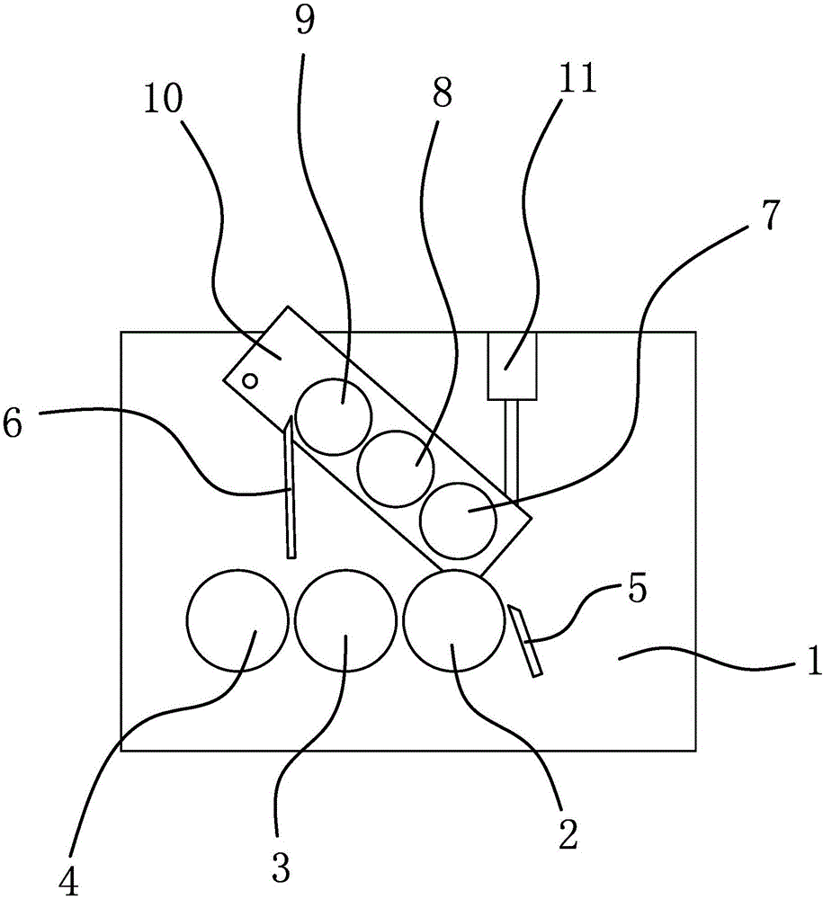
[0050] Such as figure 1 As shown, the roller grinder for this circular grinding includes a frame 1, a front roller 2, a middle roller 3 and a rear roller 4, and the above-mentioned front roller 2, middle roller 3 and rear roller 4 are all axially fixed on the frame 1 The above-mentioned front roller 2, middle roller 3 and rear roller 4 are arranged in parallel in the horizontal direction and there is a gap for the passage of ink or slurry between two adjacent rollers. The above-mentioned front roller 2, middle roller 3 and rear roller 4 A grinding part for grinding ink is formed, and an ink transfer mechanism is also connected to the frame 1, and the ink transfer mechanism is located on the upper part of the grinding part, and the front roller 2 has a scraper 5 for collecting ink or slurry There is a scraper 2 6 between the rear roller 4 and the middle roller 3, and the edge of the scraper 6 is close to the ink transfer mechanism, and the ink or slurry at the ink transfer mech...

Embodiment 2

[0064] The structure and principle of this embodiment are basically the same as that of Embodiment 1, the difference is that:

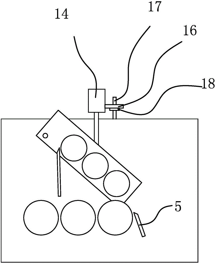
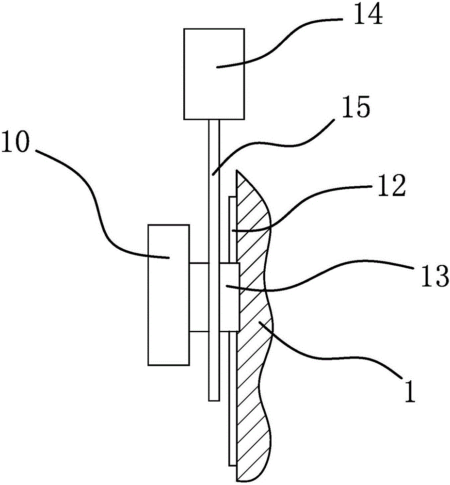
[0065] Such as figure 2 with image 3 with Figure 4 Shown, described frame 1 has an ink transfer frame 10, above-mentioned ink transfer roller one 7, ink transfer roller two 8 and ink transfer roller three 9 are all axially fixed on the ink transfer frame 10, the machine Also have the guide rail 12 that vertical direction is arranged on the frame 1, have the slide block 13 that is embedded in above-mentioned guide rail 12 places on the above-mentioned ink transfer frame 10, also have a motor 14 on the described frame 1, be fixedly connected with on the motor 14 rotating shafts A threaded mandrel 15 parallel to the guide rail 12, the slider 13 is sleeved on the threaded mandrel 15 and the two are screwed together.

[0066] The motor 14 is fixedly connected to an adjustment block 16 , and there is a gap adjustment mechanism between the adjustment b...


PUM


Abstract

The present invention provides a roll grinding machine grinding in a circulating way, belonging to the technical field of machinery. The present invention solves the problem of low automation degree in the prior art. The roll grinding machine grinding in a circulating way comprises a machine frame, a front roller, a middle roller and a rear roller. The front roller, the middle roller and the rear roller are all axially fixedly connected to the machine frame. The front roller, the middle roller and the rear roller are disposed in parallel along the horizontal direction and clearances through which oil ink or paste passes exist between every two adjacent rollers. The front roller, the middle roller and the rear roller form a grinding portion for grinding the oil ink. The machine frame is also connected with an ink delivery mechanism. The ink delivery mechanism is positioned at the upper part of the grinding portion. The front roller is provided with a scraper I for collecting the oil ink or paste. A scraper II is disposed between the rear roller and the middle roller, and an edge of the scraper II is close to the ink delivery mechanism. The roll grinding machine grinding in a circulating way is compactly structured and highly automated.

Description

technical field [0001] The invention belongs to the technical field of machinery and relates to a roller grinder for circular grinding. Background technique [0002] With the advancement of electronic technology, the application of various pastes or inks in thick film, photovoltaic and other fields is increasing. In the production process of slurry or ink, repeated grinding by roller mill is the most important part of the processing procedure. The three-roll mill is a common type of roller mill. [0003] The working principle of the three-roller mill: the three-roller mill achieves the grinding effect on the slurry or ink through the mutual extrusion of the surfaces of the three horizontal rollers and the friction at different speeds. Three-roll mill is the most effective grinding and dispersing equipment for high-viscosity materials. [0004] During the grinding process, the material to be processed needs to be added to the equipment intermittently. The traditional opera...

Claims


Application Information

Patent Timeline
IPC IPC(8): B02C4/04B02C4/40B02C4/28
CPCB02C4/04B02C4/28B02C4/40
Inventor 宗小林
Owner 常熟东南高新技术创业服务有限公司
Why Eureka
Try Eureka