Portable spraying machine
A spraying machine, portable technology, applied in the direction of spraying device, liquid spraying device, etc., can solve the problems of low work efficiency, short spraying range, small spraying area, etc., and achieve high working efficiency, long spraying range and large spraying area.
- Summary
- Abstract
- Description
- Claims
- Application Information
AI Technical Summary
Problems solved by technology
Method used
Image
Examples
specific Embodiment approach 1
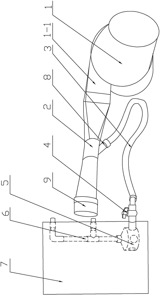
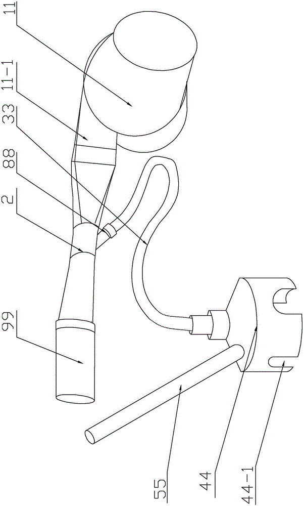
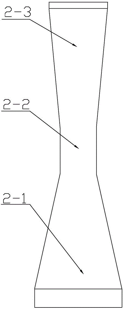
[0013] Specific implementation mode one: combine figure 1 and image 3 Describe this embodiment, a portable sprinkler in this embodiment, including a high-pressure blower 1, an injector 2, a hose 3, a manual valve 4, a first mixing chamber 5, a first air intake pipe 6 and a back barrel 7, and The ejector 2 includes a receiving chamber 2-1, a mixing chamber 2-2 and a diffusion chamber 2-3, the receiving chamber 2-1 of the ejector 2 communicates with the air outlet 1-1 of the high-pressure fan 1, and the mixing chamber 2-2 The side wall is fixedly connected with the connection port 8 communicating with the mixing chamber 2-2, and one end of the hose 3 is communicated with the connection port 8, and the other end of the hose 3 is communicated with the first mixing chamber 5 through the manual valve 4, and the first The side wall of the mixing chamber 5 is provided with a plurality of first through holes 5-1, the top of the first mixing chamber 5 communicates with the gas outlet ...
specific Embodiment approach 2
[0027] Specific implementation mode two: combination figure 1 and Figure 4 Referring to this embodiment, the first air inlet pipe 6 is an F-shaped structure, including an air outlet end 6-1 at the bottom and two air inlet ends 6-2 at the upper part. In such a design, the two intake ports 6-2 both play the role of intake air, and at the same time, the pipeline where the lower intake port 6-2 is located also serves to support and fix the entire first intake pipe 6 and the first mixing chamber 5. Function, to avoid the position deformation of the first air intake pipe 6 and the first mixing chamber 5 due to the extrusion of solid particles or liquid in the back barrel 7, and even affect the intake air in the first mixing chamber 5. In addition, the first air intake pipe 6 It is also more convenient for processing. Other compositions and connections are the same as those in the first embodiment.
specific Embodiment approach 3
[0028] Specific implementation mode three: combination figure 1 and figure 2 Description of this embodiment, the mixing chamber 2-2 of the injector 2 is a cylindrical structure, the receiving chamber 2-1 and the diffusion chamber 2-3 are both conical structures, the small end of the receiving chamber 2-1 and the diffusion chamber 2 The small ends of -3 are respectively affixed to the two ends of the mixing chamber 2-2. Such design, wherein the diffusion chamber 2-3 is a hollow conical structure, the conical structure of the receiving chamber 2-1 can be determined according to the shape of the air outlet 1-1 of the high-pressure fan 1, if the air outlet 1-1 of the high-pressure fan 1 If it is a rectangle, the shape of the joint between the receiving chamber 2-1 and the air outlet 1-1 of the high-pressure fan 1 is a rectangle. Other compositions and connections are the same as those in Embodiment 1 or Embodiment 2.
PUM
 Abstract
Description
Claims
Application Information
 - R&D
- Intellectual Property
- Life Sciences
- Materials
- Tech Scout
- Unparalleled Data Quality
- Higher Quality Content
- 60% Fewer Hallucinations
Browse by: Latest US Patents, China's latest patents, Technical Efficacy Thesaurus, Application Domain, Technology Topic, Popular Technical Reports.
© 2025 PatSnap. All rights reserved.Legal|Privacy policy|Modern Slavery Act Transparency Statement|Sitemap|About US| Contact US: help@patsnap.com


