
A clamping mechanism suitable for oil-edged materials and a method for clamping oil-edged materials

A clamping mechanism, oil edge technology, applied in the application, device for coating liquid on the surface, leather/skin/leather/hide chemical treatment equipment, etc. Meet the requirements of the leather oil edge market and other issues, and achieve the effect of stable movement, accurate positioning and opening

Active Publication Date: 2019-01-22
潘声君
View PDF4 Cites 2 Cited by
  • Summary
  • Abstract
  • Description
  • Claims
  • Application Information

AI Technical Summary

Problems solved by technology

[0003] At present, the clips of the automatic oil edge machine on the market all move horizontally. When targeting some small materials, they are often unable to determine the left and right directions and flatten the material, resulting in poor practicability of the automatic oil edge machine, which cannot meet the requirements of the leather oil edge market.

Method used


Image

  • A clamping mechanism suitable for oil-edged materials and a method for clamping oil-edged materials
  • A clamping mechanism suitable for oil-edged materials and a method for clamping oil-edged materials
  • A clamping mechanism suitable for oil-edged materials and a method for clamping oil-edged materials

Examples


Embodiment approach

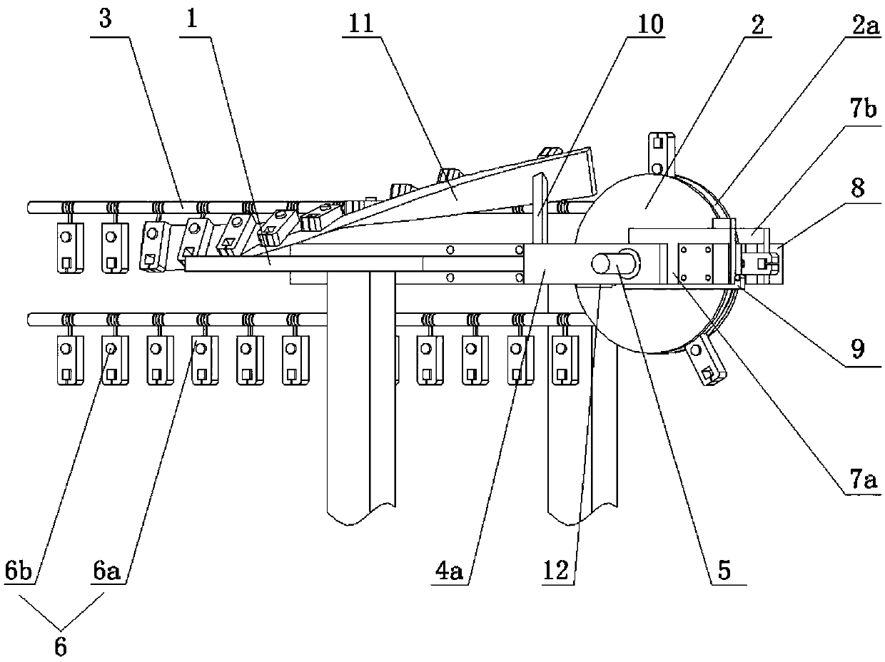
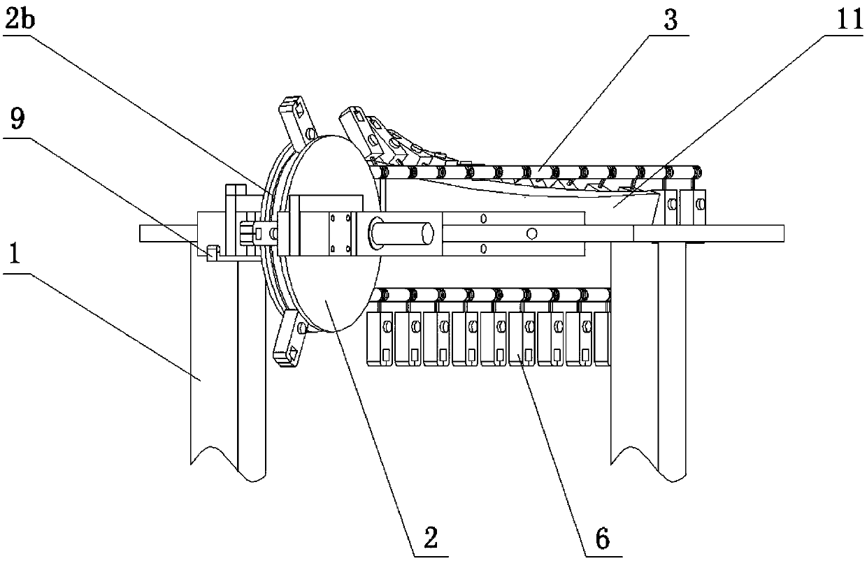
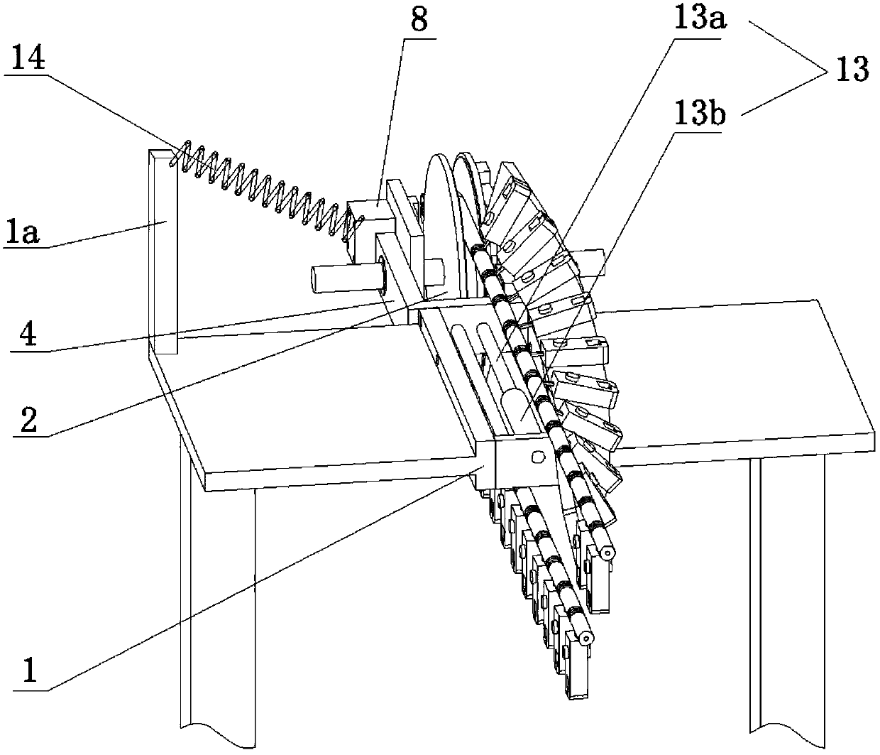
[0039] like figure 2 As shown, as the first embodiment of the present invention, the clip opening device is a clip opening cylinder 8, and the left and right sides of the turntable support frame 4 are respectively fixedly connected with a left support block 7a and a right support block 7b. The support block 7a is connected with a left open-clamp cylinder 8a, and the right support block 7b is connected with a right-open clamp cylinder 8b, which is a photoelectric induction cylinder; the side of the fixed chuck 2 is provided with the clamp detection device 9, The clip detection device 9 extends a certain distance to the front end of the fixed chuck 2. When the clip detection device 9 senses that the clip 6 moves to the middle position of the left-opening cylinder 8a and the right-opening cylinder 8b, the string-clamping rope 3 is stopped. At the same time, the left-clamping cylinder 8a and the right-clamping cylinder 8b open the clamps 6 .

[0040] like image 3 As shown, as ...


PUM


Abstract

The invention belongs to the technical field of automatic edge oiling machines, and particular relates to a clamping mechanism applicable to oil edge materials. The clamping mechanism comprises a rack, a rotating disc and a string clamp rope, clamps are arranged on the string clamp rope at intervals, the rack comprises a rotating disc support frame, a clamp guide plate, a clamp detection device and a clamp opening device, a rotating disc shaft is arranged on the rotating disc support frame, the rotating disc is connected to the rotating disc support frame through the rotating disc shaft, an annular groove is formed in the periphery of the rotating disc, the string clamp rope is arranged in the annular groove in a sleeved mode, and a power source which drives the string clamp rope to rotate around the rotating disc is connected to the string clamp rope; each clamp comprises a clamp body and a button, the width of the bottom end of each clamp body is smaller than that of the annular groove, and the width of the annular groove is smaller than that of each button. The clamping mechanism applicable to the oil edge materials is simple in structure, convenient and safe to operate and high in work efficiency and can position the clamps accurately and achieve precise processing of small materials.

Description

technical field [0001] The invention relates to the technical field of automatic oil edge machines, in particular to a clamping mechanism suitable for oil edge materials and a method for clamping oil edge materials. Background technique [0002] In the process of leather processing, after the leather material is cut, its edge is relatively rough, such as making it into a finished leather product, it is very unsightly, which affects the quality of the product. Therefore, in the subsequent process of processing leather products such as belts and handbags, it is necessary to apply a layer of oil to the edges of both sides of the belt and the edges of the leather material exposed on the handbag, that is, oil edges. [0003] At present, the clips of automatic edging machines on the market move laterally. When targeting some smaller materials, the left and right directions are often inaccurate and the material is flattened, resulting in poor practicability of the automatic edging ...

Claims


Application Information

Patent Timeline
Patent Type & Authority Patents(China)
IPC IPC(8): B05C13/00C14C15/00C14C11/00
CPCB05C13/00C14C11/00C14C15/00
Inventor 潘声君
Owner 潘声君
Learn More