
Cleaning robot for indoor guardrail of building

A technology for cleaning robots and guardrails, which is applied to manipulators, program-controlled manipulators, and manufacturing tools. It can solve the problems of poor rigid support performance, non-adjustable cleaning diameter, and low degree of automation, so as to increase rigid support performance and increase cleaning stability. , the effect of high degree of automation

Active Publication Date: 2016-08-24
湖南哈工机器人研究院有限公司
View PDF9 Cites 5 Cited by
  • Summary
  • Abstract
  • Description
  • Claims
  • Application Information

AI Technical Summary

Problems solved by technology

[0003] In order to solve the above problems, the present invention provides a building indoor guardrail cleaning robot, which can solve the problems of high labor intensity, slow cleaning speed, poor cleaning effect and low work efficiency in the existing manual cleaning of indoor guardrails. Hand-held indoor guardrail cleaning equipment needs manual cleaning, low degree of automation, small range of cleaning height adjustment, vibration of equipment during lifting and cleaning, poor cleaning stability, poor cleaning effect, poor rigid support performance, and low work efficiency , non-adjustable cleaning diameter and small application range, etc., can realize the stable automatic lifting and cleaning function of indoor guardrails, and has the advantages of no manual operation, high degree of automation, fast cleaning speed, large cleaning height adjustment range, large cleaning diameter adjustment range, and wide application range. Large size, no vibration during lifting and cleaning, good cleaning stability, good rigid support performance, good cleaning effect and high work efficiency, providing a new way to automatically clean the guardrail

Method used


Image

  • Cleaning robot for indoor guardrail of building
  • Cleaning robot for indoor guardrail of building
  • Cleaning robot for indoor guardrail of building

Examples


Embodiment Construction

[0029] In order to make the technical means, creative features, goals and effects achieved by the present invention easy to understand, the present invention will be further described below in conjunction with specific illustrations.

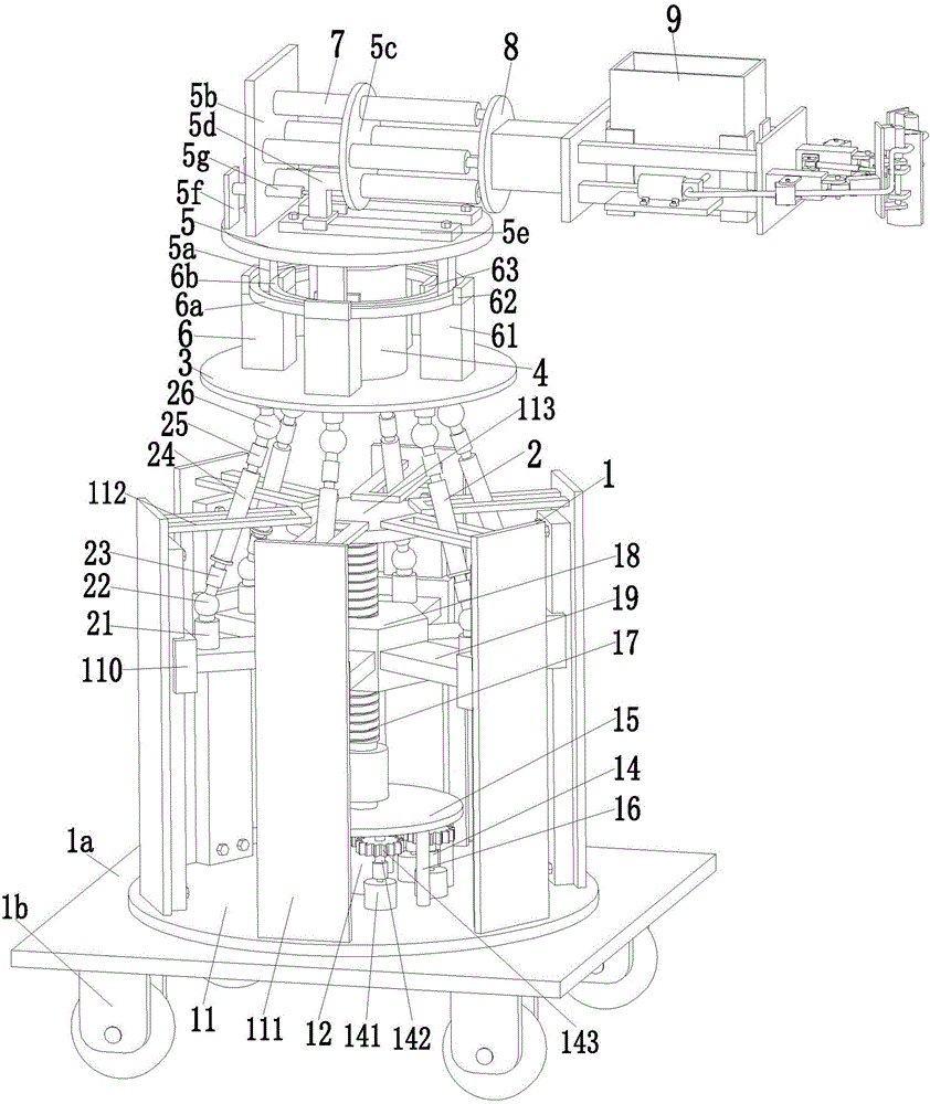
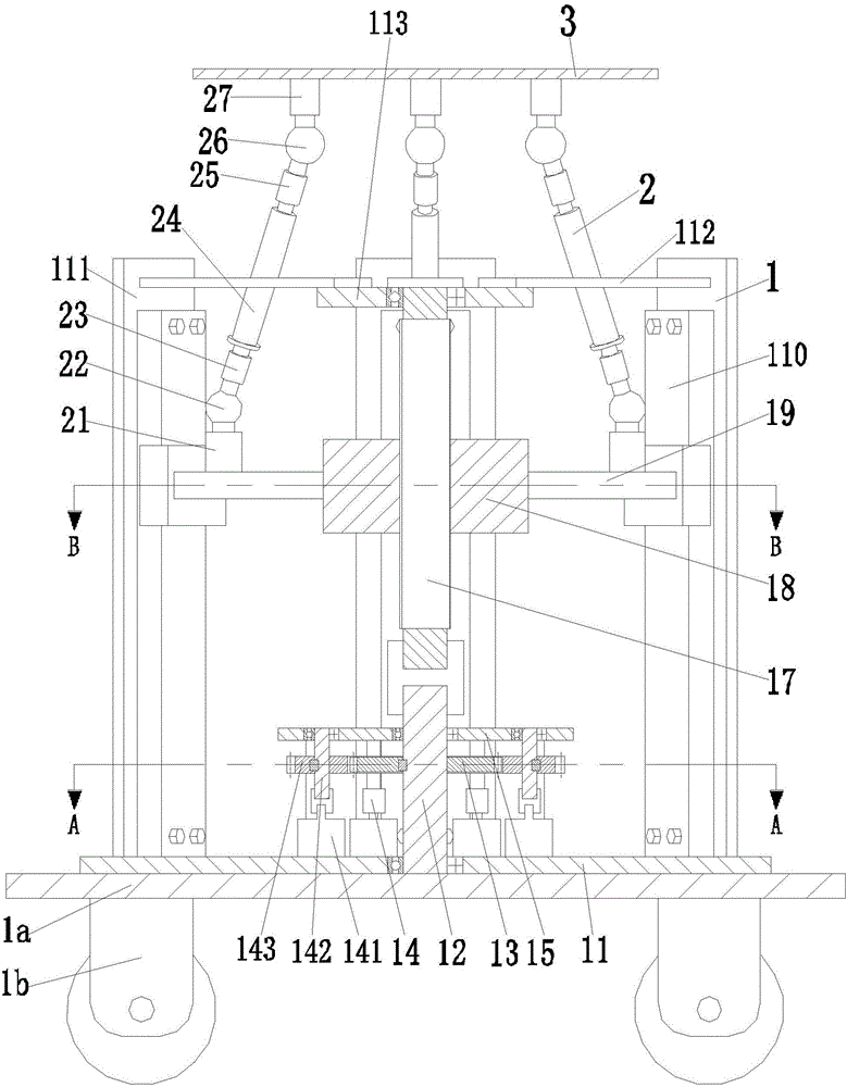
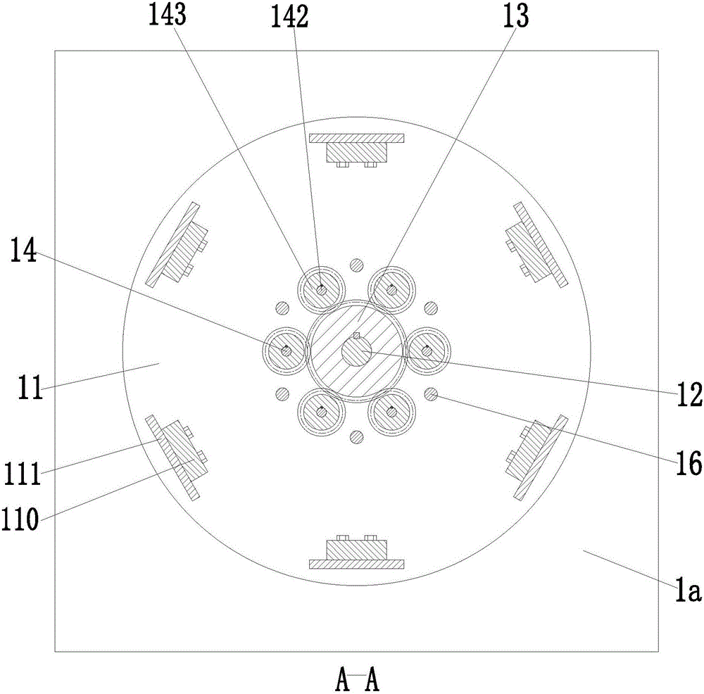
[0030] like Figure 1 to Figure 10 As shown, a building indoor guardrail cleaning robot includes a fixed frame 1, the lower end surface of the fixed frame 1 is provided with a bottom plate 1a, and the lower end surface of the bottom plate 1a is symmetrically provided with four universal wheels 1b, through which four universal wheels 1b are arranged. The steering wheel 1b can move the present invention to the edge of the required cleaning guardrail at will, and the operation is simple and convenient. Six parallel branch chains 2 are respectively installed on the fixed frame 1, and the upper ends of the six parallel branch chains 2 are evenly installed on the upper platform 3. The fixed frame 1 includes a lower platform 11, the middle part of the ...


PUM


Abstract

The invention relates to a cleaning robot for an indoor guardrail of a building. The cleaning robot comprises a fixed rack, wherein a base plate is arranged on the lower end surface of the fixed rack; four universal wheels are symmetrically arranged on the lower end surface of the base plate; six parallel-connected branch chains are correspondingly mounted on the fixed rack; the upper ends of the six parallel-connected branch chains are uniformly mounted on an upper platform; a rotary motor is mounted in the middle of the upper end surface of the upper platform through a motor seat; a rotary platform is fixedly mounted at the output end of the rotary motor; four supporting column frames are uniformly welded on the upper end surface of the upper platform along the axial direction; a first rotary bearing and a second rotary bearing are mounted on the four supporting column frames; four rotary supporting columns are uniformly mounted between the first rotary bearing and the second rotary bearing; the top ends of the four rotary supporting columns are symmetrically mounted on the lower end surface of the rotary platform. The cleaning robot can realize stable automatic lifting and cleaning functions for the indoor guardrail, and a new way for automatically cleaning the guardrail is provided.

Description

technical field [0001] The invention relates to building cleaning equipment, in particular to a building indoor guardrail cleaning robot. Background technique [0002] With the continuous development of China's economy, high-rise buildings can be seen everywhere. In order to ensure the safety of users, stainless steel guardrails are usually installed before the indoor glass of high-rise buildings. The stainless steel guardrails need to be wiped and cleaned regularly. However, due to the existing indoor stainless steel There are a large number of guardrails, which greatly increases the workload of cleaning personnel, and the manual cleaning of indoor stainless steel guardrails has defects such as slow cleaning speed, poor cleaning effect, and low work efficiency; although most guardrail cleaning equipment in the existing market is aimed at Outdoor stainless steel guardrails such as road guardrails and greening guardrails are designed, but there are still a small number of ind...

Claims


Application Information

Patent Timeline
IPC IPC(8): B25J11/00B25J5/00B25J9/00
CPCB25J5/007B25J9/0057B25J11/0085
Inventor 程岚
Owner 湖南哈工机器人研究院有限公司
Learn More