Eureka AIR delivers breakthrough ideas for toughest innovation challenges, trusted by R&D personnel around the world.

Secondary fast forming machine for sole material

A shoe sole material and molding machine technology, which is applied to household components, household appliances, other household appliances, etc., can solve the problems of the threat of the operator's working environment, the inefficiency of equipment use, the loss of energy from the transfer plate, etc., and achieve the temperature change of the working environment. Low, reduce the frequency of failures, improve the effect of the working environment

Active Publication Date: 2016-08-24
泉州大展机械有限公司
View PDF4 Cites 10 Cited by
  • Summary
  • Abstract
  • Description
  • Claims
  • Application Information

AI Technical Summary

Problems solved by technology

Therefore, the traditional EVA secondary molding machine has the following disadvantages: 1. The operator needs to manually transfer the mold from the high temperature area to the cooling area while the mold is still at high temperature, which poses a greater threat to the operator's working environment
2. The efficiency of equipment use is low. At the same time, only one station works in the heating station and cooling station in the same group, and the utilization rate of equipment is low.
The molding machine also has the following unreasonable points: 1. From the perspective of energy, the cooling of the transfer plate after heating will inevitably cause energy loss
2. After investigation, the rapid change of the transfer plate between hot and cold will affect the overall stability of the machine, and the failure rate is high
3. The replacement of the mold is not convenient enough, the upper mold is always in the heat transfer area, and it is difficult for the operator to replace

Method used


Image

  • Secondary fast forming machine for sole material
  • Secondary fast forming machine for sole material
  • Secondary fast forming machine for sole material

Examples


Embodiment approach

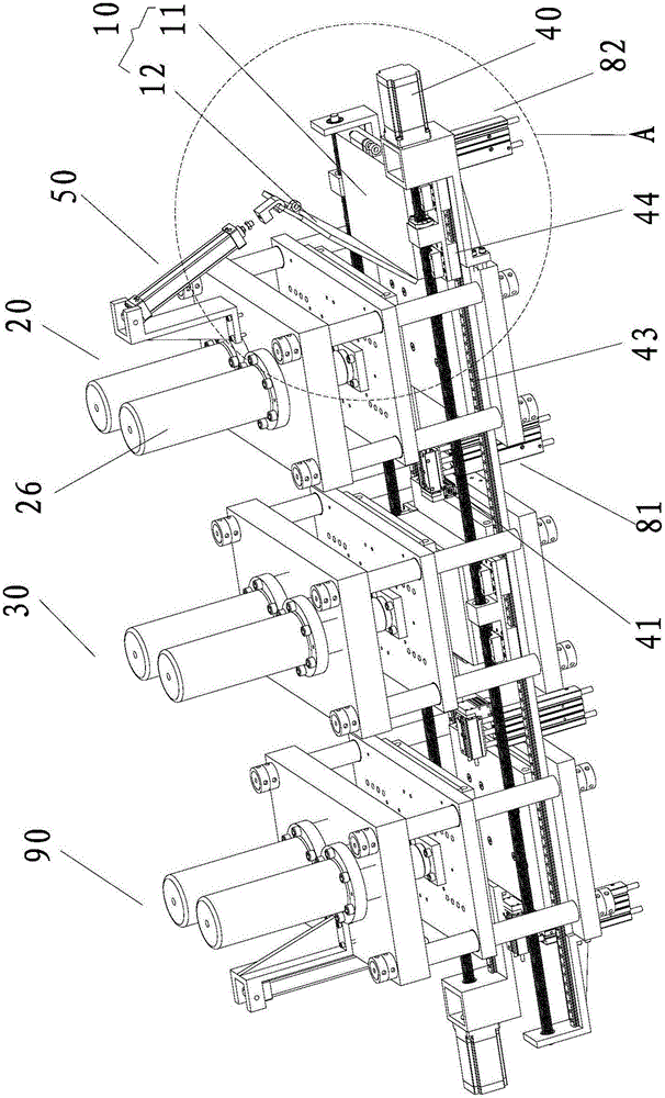
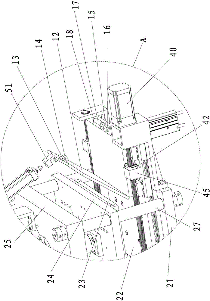
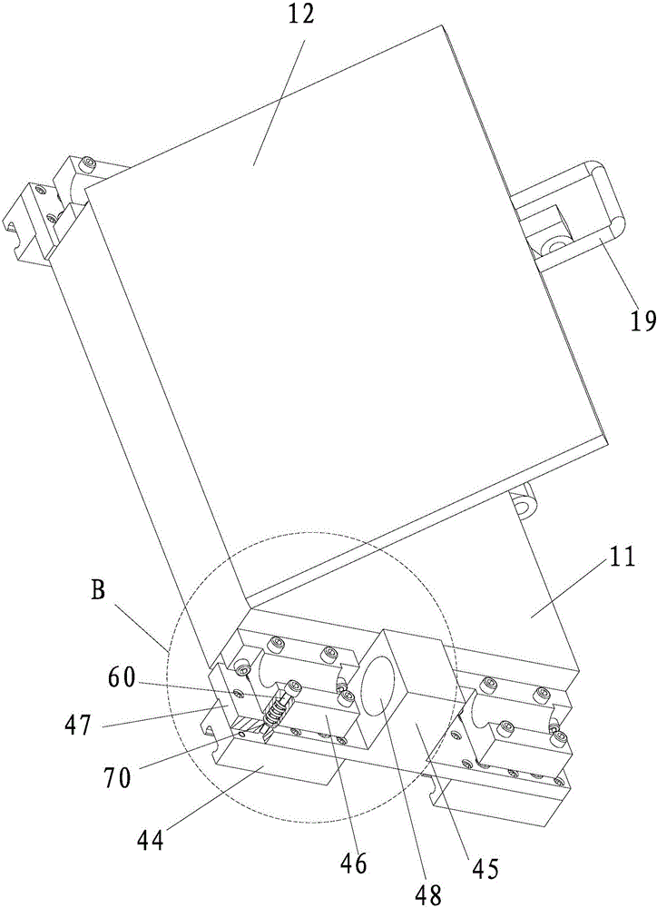
[0078] As the first embodiment of the bolt driving mechanism, the bolt driving mechanism includes a No. 1 locking mechanism 81 for pushing the No. 1 bolt 18 into the No. 1 lower connecting hole 16. Between the cooling mold station 20 and the heating mold station 30, a No. 1 unlocking mechanism 82 for pushing the No. 1 latch 18 away from the No. 1 lower connecting hole 16 is also included. The No. 1 unlocking mechanism 82 corresponds to the No. 1 cooling mold station 20 set up. With this structure, automatic mold locking and automatic mold opening can be realized. During operation, before the heating of the No. 1 mold 10, the No. 1 latch 18 is inserted into the No. 1 upper connection hole 14 and the No. 1 lower part through the No. 1 mold locking mechanism 81. In the connection hole 16, the locking of the No. 1 mold box 11 and the No. 1 mold cover 12 is realized. After the No. 1 mold 10 is cooled, the No. 1 latch 18 is connected from the No. 1 upper connection hole 14 to the No...


PUM


Abstract

The invention relates to a secondary fast forming machine for a sole material. The secondary fast forming machine for the sole material comprises a mold for containing the sole material, a heating mold station for heating the mold, and a first cooling mold station for cooling the mold and further comprises a second cooling mold station for cooling the mold; the first cooling mold station and the second cooling mold station are arranged on the two sides of the heating mold station; the mold comprises a first mold body corresponding to the first cooling mold station and a second mold body corresponding to the second cooling mold station; an automatic transferring mechanism is further included; the first mold body can be arranged on the automatic transferring mechanism in the manner that the first mold body moves between the first cooling mold station and the heating mold station; and the second mold body can be arranged on the automatic transferring mechanism in the manner that the second mold body moves between the second cooling mold station and the heating mold station. The forming machine can greatly improve the work environment of an operator, relieve the workloads of the operator and achieve automatic forming of soles; and meanwhile the energy utilizing rate is increased, and efficient, energy-saving, environment-friendly and reasonable energy transmission is achieved.

Description

technical field [0001] The invention belongs to the field of shoe material molding equipment, and in particular relates to a secondary rapid molding machine for shoe sole materials. Background technique [0002] EVA secondary molding is an important part of the shoe sole mold process. Its production efficiency directly affects the profit level of the enterprise, especially in the shoe material industry, it is an important factor affecting the cost of shoe materials, so it has become a constraint for enterprises. key to development. [0003] The existing EVA secondary molding machines are mainly divided into two categories, namely the traditional type and the fast type, but both types inevitably have some disadvantages. [0004] The traditional EVA secondary molding machine adopts a sub-station heating and cooling process, and its heating position and cooling position are fixed. Therefore, each molding machine is set up in pairs and lined up, where each heating station need...

Claims


Application Information

Patent Timeline
IPC IPC(8): B29C44/34B29L31/50
CPCB29C44/3415B29L2031/504
Inventor 许德强许明凯
Owner 泉州大展机械有限公司
Why Eureka
Eureka Blog
Learn More