Auxiliary press roller and forming machine connector press roller with same

A technology of auxiliary pressure and main pressure roller, which is applied in the field of tire manufacturing and can solve problems such as high pressure of pressure rollers

Active Publication Date: 2016-08-24
QINGDAO SENTURY TIRE CO LTD
View PDF3 Cites 5 Cited by
  • Summary
  • Abstract
  • Description
  • Claims
  • Application Information

AI Technical Summary

Problems solved by technology

The existing joint pressure roller of the forming machine is composed of multiple pieces (usually 6 pieces) of roll pieces. In order to ensure the pressing force of the joint, a strong spring is installed under each piece of roll piece; however, such a setting will make the pressure of the pressure roller very high. Large, the surface of the pressure roller is almost tangent to the surface of the forming drum, that is, the surface of the pressure roller and the surface of the forming drum are in point contact. The pressing form of this joint is very easy to push the end of the tread joint out

Method used


Image

  • Auxiliary press roller and forming machine connector press roller with same
  • Auxiliary press roller and forming machine connector press roller with same
  • Auxiliary press roller and forming machine connector press roller with same

Examples


Embodiment 1

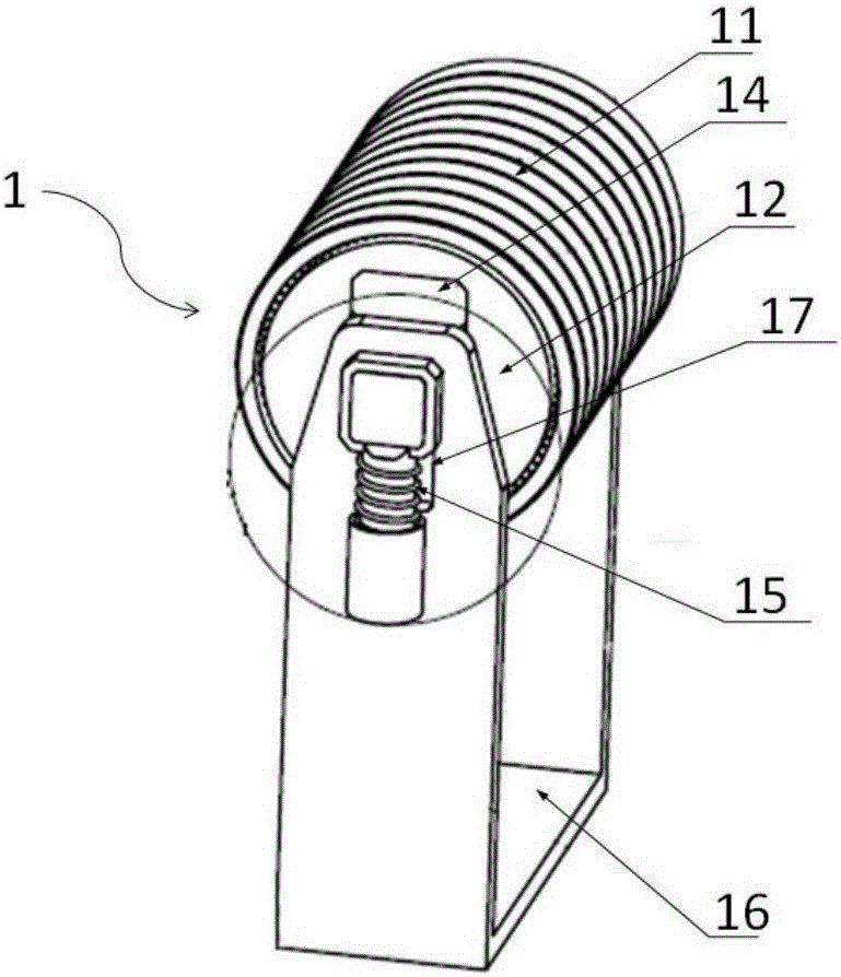
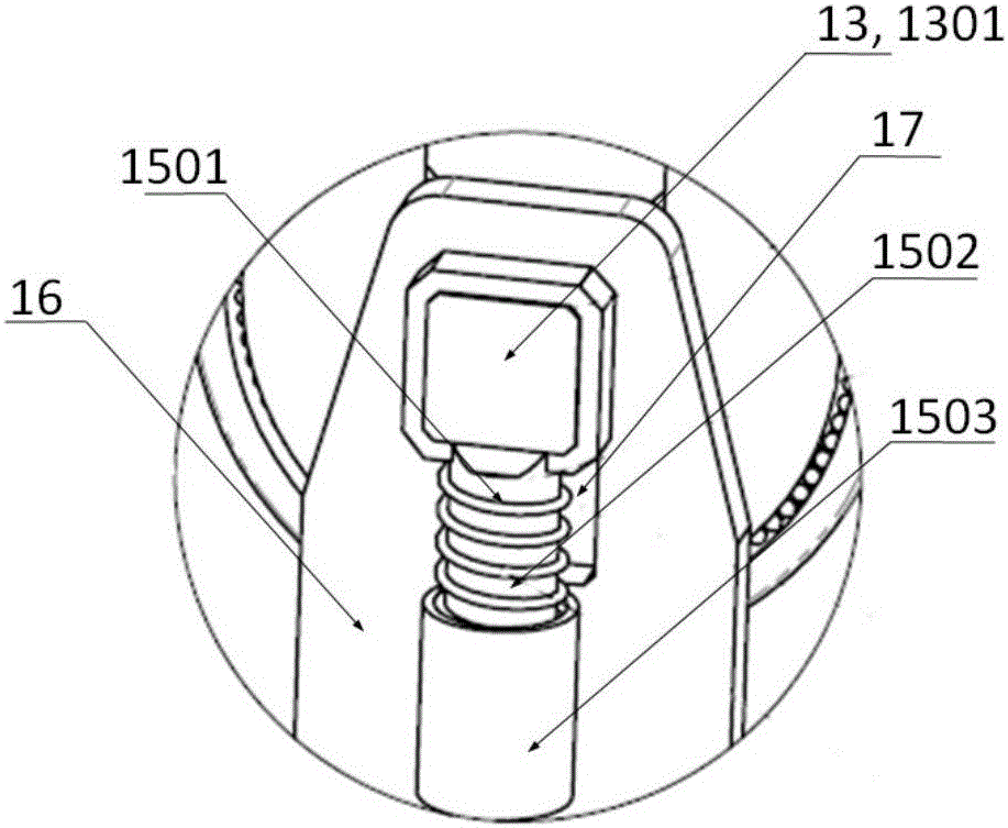
[0049] Such as Figure 1-4 As shown, a kind of auxiliary pressure roller 1 comprises roller sheet 11, roller 12, roller shaft 13, elastic layer 14, supporting device 15, base 16 and guide groove 17; Wherein, roller sheet 11 is arranged on the outside of roller 12 and Surrounding the roller 12; the roller shaft 13 is longitudinally arranged inside the roller 12, and the elastic layer 14 is also arranged along the longitudinal direction above the roller shaft 13, and the elastic layer 14 is located in the wrapping range of the roller sheet 11; the base 16 is located at both ends of the roller shaft 13, Supporting the roller shaft 13, guide grooves 17 are provided on both sides of the base 16, and the openings of the guide grooves 17 are in the up and down direction; the two ends of the roller shaft 13 are roller shaft ends 1301, which extend outward from the guide groove 17, and the roller shaft ends A supporting device 15 is provided below 1301, and the supporting device 15 is ...

Embodiment 2

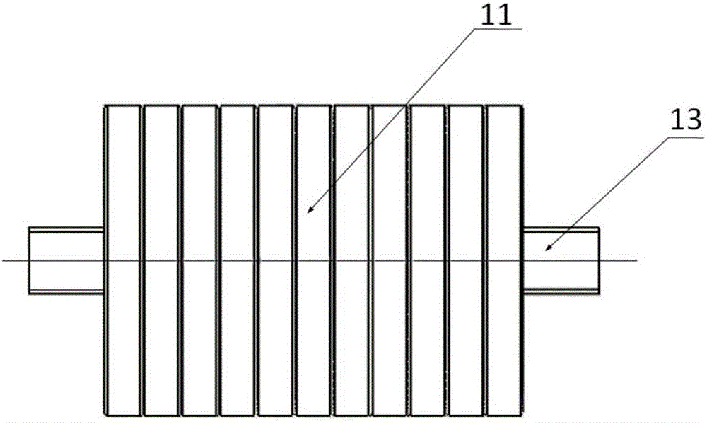
[0052] On the basis of embodiment 1, the quantity of roller sheet 11 is 8, and its structure is uniform, is arranged on roller 13 successively; Elastic layer 14 is elastic rubber layer, and its elastic force is equivalent to the spring that elastic constant is 1N / mm.

Embodiment 3

[0054] On the basis of embodiment 1 or 2, such as Figure 4 As shown, a rolling element 18 is arranged between the roller sheet 11 and the roller 12, and the rolling element 18 is used to support the rotation of the roller sheet 11 around the roller 12; the relationship between the roller sheet 11, the rolling element 18 and the roller 12 is equivalent to a rolling bearing Relationship.


PUM

PropertyMeasurementUnit
Elastic coefficientaaaaaaaaaa

Abstract

The invention relates to a press roller for tire manufacturing, in particular to an auxiliary press roller and a forming machine connector press roller with the same, and belongs to the field of tire manufacturing; the auxiliary press roller comprises a roller plate, a roller barrel, a roller shaft, an elastic layer, support devices, a base and a guide channel, wherein the roller plate is arranged outside the roller barrel and encloses the roller barrel, the roller shaft is disposed in the roller barrel, and the elastic layer is disposed above or outside the roller shaft and is positioned in a covering range of the roller plate; two ends of the roller shaft are roller shaft ends, the support devices are arranged below the roller shaft ends, and the support devices are positioned on the base and are elastic so that the roller shaft can move up and down according to its load-carrying condition.

Description

technical field [0001] The invention relates to a pressure roller for manufacturing tires, in particular to an auxiliary pressure roller and a forming machine joint pressure roller with the auxiliary pressure roller, belonging to the field of tire manufacturing. Background technique [0002] Generally, the tire molding process requires that the sidewall joint form of the sidewall and the inner liner composite is lap joint, and the sidewall joint process requirements are controlled at 3-4 mm, but this is prone to defects such as tire bulges and dents. The above problems can be effectively avoided by reducing the size of the sidewall joints or using butt joints for the joints. However, after the sidewall joints are reduced, the existing joint pressure rollers of the forming machine will push the end of the sidewall joints away when rolling the sidewall joints, so that when the green tire (the embryo before vulcanization) is turned up cracking. [0003] In addition, many dome...

Claims


Application Information

Patent Timeline
IPC IPC(8): B29D30/28B29D30/30B29D30/14B29D30/16
CPCB29D30/14B29D30/16B29D30/28B29D30/30
Inventor 秦龙潘友尚常慧敏
Owner QINGDAO SENTURY TIRE CO LTD
Why Eureka
Try Eureka