Upper vehicle-body structure of vehicle

一种车辆、车身的技术,应用在上部车身结构领域,达到提高操纵稳定性、改善振动衰减性能、提高扭转刚性的效果

Inactive Publication Date: 2016-08-24
MAZDA MOTOR CORP
View PDF9 Cites 14 Cited by
  • Summary
  • Abstract
  • Description
  • Claims
  • Application Information

AI Technical Summary

Problems solved by technology

[0005] However, the upper body structures of the vehicles disclosed in the above-mentioned Patent Documents 1 and 2 are all structures for improving the surface rigidity of the roof itself, rather than structures proposed for the purpose of improving the torsional rigidity of the entire vehicle body. further discussion

Method used


Image

  • Upper vehicle-body structure of vehicle
  • Upper vehicle-body structure of vehicle
  • Upper vehicle-body structure of vehicle

Examples


no. 1 approach

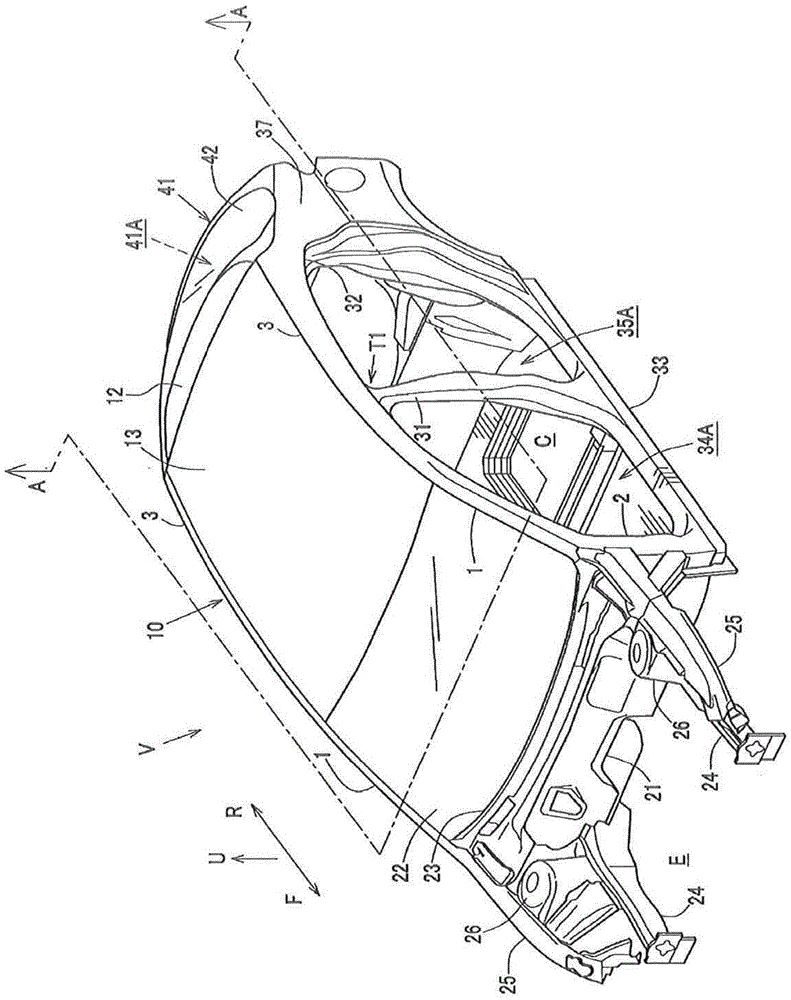
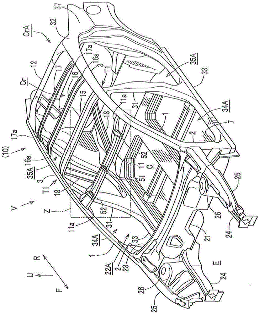
[0031] Such as figure 1 and figure 2 As shown, in the upper part of the vehicle V according to the first embodiment, front pillars 1, 1 extending from the front lower part to the rear upper part are provided on both sides in the vehicle width direction. The hinge column 2,2 that direction extends is connected.

[0032] The front pillar 1 is a body rigid member having a closed section by joining the front pillar inner and the front pillar outer, and the hinge pillar 2 is a body rigid member having a closed section by joining the hinge pillar inner and the hinge pillar outer.

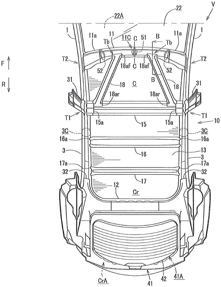
[0033] Such as Figure 1 to Figure 3 As shown, a pair of left and right roof rails 3, 3 (roof side rails) extending in the front and rear direction of the vehicle are continuously formed at the rear ends of the above-mentioned left and right front pillars 1, 1. The upper ends of 1 are bridged with front roof beams 11 extending along the vehicle width direction (refer to figure 2 , image 3 ), and t...

no. 2 approach

[0074] Such as Figure 8 As shown, the vehicle Va of the second embodiment is a vehicle provided with a rear inclined roof reinforcement 61 instead of the rear first vehicle width direction roof reinforcement 16 and the rear roof reinforcement 61 of the vehicle V of the first embodiment. The second side roof reinforcement 17 in the vehicle width direction, the rear portion of the rear sloped roof reinforcement 61 is coupled to the rear roof cross member 12, and the rear sloped roof reinforcement 61 is positioned so as to be more positioned toward the vehicle front side. The widthwise outer side extends obliquely.

[0075] Specifically, the rear sloping roof reinforcement 61 has a pair of left and right frame members inclined so as to be located inward in the vehicle width direction toward the vehicle rear side, the rear end portions of the pair of frame members are joined to each other, and the one pair of frame members The counter frame member is coupled to the center portio...

no. 3 approach

[0082] Such as Figure 9 As shown, the vehicle Vb of the third embodiment is provided with a front cross-shaped roof reinforcement 71 extending in the vehicle width direction in a cross-shaped manner in a plan view of the vehicle between the pair of left and right roof side rails 3, 3 to In place of the front side vehicle width direction roof reinforcement 15 (refer to image 3 ).

[0083] The front cross-shaped roof reinforcement 71 has an intersection portion located approximately in the middle in the vehicle width direction between the pair of roof side rails 3 , 3 and in the approximately middle in the front-rear direction between the front roof cross member 11 and the center pillar 31 . . Furthermore, the front cross-shaped roof reinforcement 71 has intersecting portions that intersect with the left and right front sloping roof reinforcements 18 , 18 , respectively.

[0084] Furthermore, the front side cross-shaped roof reinforcement 71 is integrally formed by connecti...


PUM


Abstract

There are provided a pair of roof rails, a roof panel, a front header, a pair of front pillars, and a pair of center pillars, and a pair of front inclination roof reinforcements provided at a lower face of the roof panel. Each of the front inclination roof reinforcements is configured to extend obliquely from its front portion which is joined to the front header to its rear portion which is positioned on an outward side, in a vehicle width direction, relative to the front portion and joined to a portion located in the vicinity of a joint portion of the center pillar and the roof rail. Thereby, the torsional rigidity of a vehicle body can be properly improved, so that the maneuverability / stability of a vehicle can be improved.

Description

technical field [0001] The present invention relates to an upper body structure of a vehicle. The upper body structure includes: a pair of left and right roof side rails, which are arranged on the left and right ends of the roof of the vehicle body so as to extend along the front and rear directions of the vehicle; between the pair of left and right roof side beams; the front roof cross beam is arranged to extend in the vehicle width direction along the front part of the roof panel; The roof side beam extends downward; the center pillar is arranged behind the front pillar, the upper part is combined with the roof side beam, and extends downward from the roof side beam. Background technique [0002] As the upper body structure of a vehicle, there are known Japanese Patent Laid-Open Publication No. 2014-58224 (hereinafter referred to as Patent Document 1) and Japanese Patent Laid-Open Publication No. 2002-248943 (hereinafter referred to as Patent Document 2). The structure sh...

Claims


Application Information

Patent Timeline
Patent Type & Authority Applications(China)
IPC IPC(8): B62D25/00B62D25/04B62D25/06
CPCB62D25/00B62D25/04B62D25/06
Inventor 中村岳司川崎敬三佐藤健一
Owner MAZDA MOTOR CORP
Why Eureka
Try Eureka