Low implantation line double-wire section terminal spine type bearing rail beam limiting structure in medium and low speed magnetic levitation transportation engineering

A technology for traffic engineering and low-lying lines, which is applied to roads, tracks, ballast layers, etc., can solve problems affecting the normal operation of maglev vehicles, settlement after inconsistency after construction, and affecting the smoothness of F rails, etc., to facilitate maintenance and maintenance, Avoid the unevenness of the rail surface and increase the effect of lateral stability

Inactive Publication Date: 2016-08-24
CHINA RAILWAY SIYUAN SURVEY & DESIGN GRP
View PDF6 Cites 19 Cited by
  • Summary
  • Abstract
  • Description
  • Claims
  • Application Information

AI Technical Summary

Problems solved by technology

[0004] In order to prevent excessive temperature stress and uneven settlement, the traditional rail-bearing beam structure generally adopts expansion joints of 10-30m per section. Due to the influence of various factors, the quality is relatively difficult to control, so it is easy to produce uneven settlement under the action of load and various natural and various natural factors. It is inevitable that there will be inconsistent post-construction settlement between adjacent rail bearing beams, resulting in the occurrence of Wrong platform, which will affect the smoothness of F track, and may even cause problems such as wrong platform and deformation of F track, which will affect the normal operation of maglev vehicles in severe cases

Method used


Image

  • Low implantation line double-wire section terminal spine type bearing rail beam limiting structure in medium and low speed magnetic levitation transportation engineering
  • Low implantation line double-wire section terminal spine type bearing rail beam limiting structure in medium and low speed magnetic levitation transportation engineering
  • Low implantation line double-wire section terminal spine type bearing rail beam limiting structure in medium and low speed magnetic levitation transportation engineering

Examples


Embodiment Construction

[0023] In order to make the object, technical solution and advantages of the present invention clearer, the present invention will be further described in detail below in conjunction with the accompanying drawings and embodiments. It should be understood that the specific embodiments described here are only used to explain the present invention, not to limit the present invention. In addition, the technical features involved in the various embodiments of the present invention described below can be combined with each other as long as they do not constitute a conflict with each other.

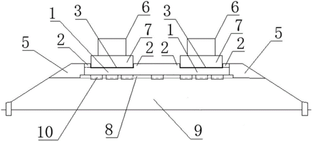
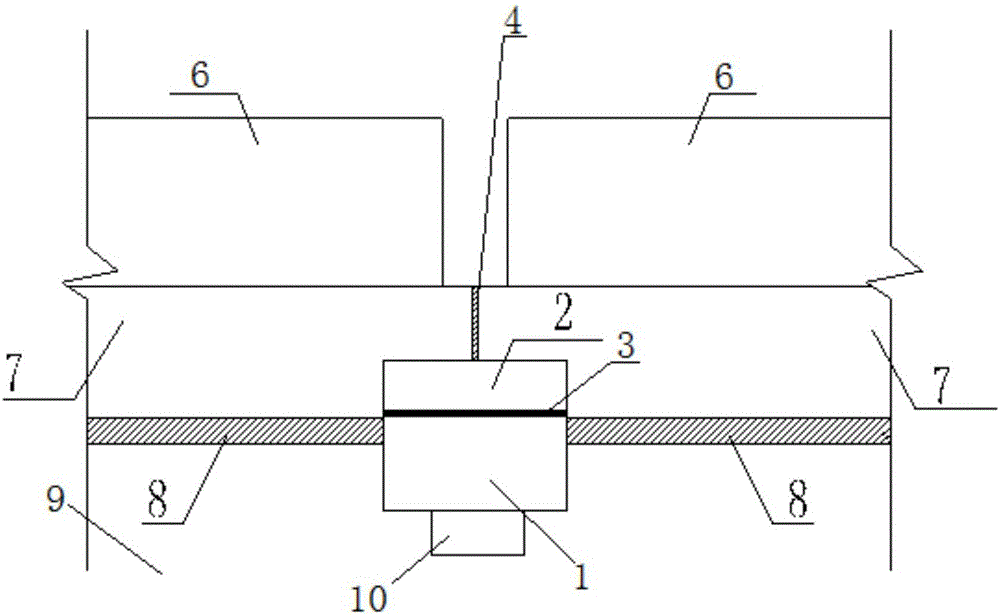
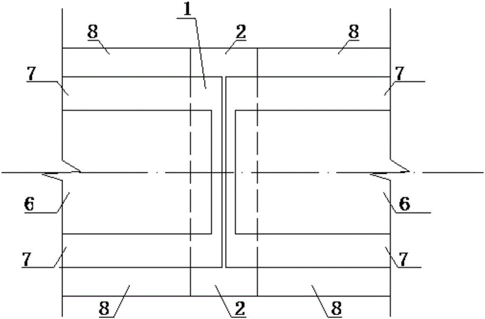
[0024] refer to Figure 1 ~ Figure 3 , the middle and low speed maglev traffic engineering low-set line double-line section end-stab type bearing beam internode limit structure, including two single-line line structures, and each single-line line structure includes subgrade filler 9 under the rail-bearing beam, bearing rail Beam underlayment 8, two adjacent rail-bearing beams, vertical stagger-...


PUM


Abstract

The invention discloses a low implantation line double-wire section terminal spine type bearing rail beam limiting structure in medium and low speed magnetic levitation transportation engineering. The limiting structure comprises bearing rail beam lower subgrade filling, a bearing rail beam underlayer, two adjacent sections of bearing rail beams, vertical slab staggering prevention lapping plates, horizontal slab staggering prevention bosses and a bearing rail beam backfill material, wherein the vertical slab staggering prevention lapping plates are fixedly arranged on the bearing rail beam lower subgrade filling, and the lower ends of the vertical slab staggering prevention lapping plates stretch into the bearing rail beam lower subgrade filling. According to the invention, slab staggering prevention reinforced concrete lapping plates are arranged at bearing rail beam section positions, the bearing rail beam is arranged on the same reinforced concrete slab staggering prevention plate with a certain rigidity, and the problem that the rail surface is unsmooth due to differential settlement of the bearing rail beam lower subgrade is effectively solved.

Description

technical field [0001] The invention belongs to the field of medium and low-speed maglev low-set lines, and more specifically relates to an end-stab type internode space-limiting structure of a low-set line of a medium-low-speed maglev traffic engineering double-track section. Background technique [0002] Medium and low-speed maglev rail transit is a new type of transportation. At present, there are few research results at home and abroad, and there are even fewer lines in operation around the world. At present, there are only the commercial operation line of the medium and low speed maglev railway in Japan in March 2005-Eastern Hills Line and the commercial operation line of the medium and low speed maglev railway in South Korea in June 2014. At present, China's medium and low-speed maglev transportation only has the National University of Defense Technology test line, the Qingchengshan test line, and the Tangshan test line, but there are no official lines in operation, an...

Claims


Application Information

Patent Timeline
Patent Type & Authority Applications(China)
IPC IPC(8): E01B25/30E01B1/00
CPCE01B25/30E01B1/00
Inventor 郭建湖姜鹰李小和赵新益姚洪锡李巍王勇刚杨辉建
Owner CHINA RAILWAY SIYUAN SURVEY & DESIGN GRP
Why Eureka
Try Eureka