

A pressure-bearing enlarged head anti-floating anchor structure and its construction method
A technology of anti-floating anchor rod and expanding head, which is applied in the direction of infrastructure engineering, construction, protection devices, etc., can solve the problems of poor stability of the anchoring end and limited structural strength of the anchoring end, etc., to improve lateral friction and improve anti-floating Capacity and stability, effect of increasing radial area
Active Publication Date: 2022-05-31
福建省水利水电工程局有限公司
View PDF0 Cites 0 Cited by
- Summary
- Abstract
- Description
- Claims
- Application Information
AI Technical Summary
Problems solved by technology
[0004] In view of the above-mentioned related technologies, the inventor believes that the structural strength of the anchoring end of the plain concrete body is limited, and the stability of the anchoring end is poor, which leads to limitations in the anti-floating ability of the anchor rod
Method used
View moreImage
Smart ImageViewing Examples

Examples
Embodiment 2
Login to View More PUM
 Abstract
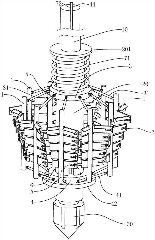
The application relates to a pressure-bearing enlarged head anti-floating anchor structure and its construction method, which includes an anchor body, a shaft sleeve and a plurality of vertical ribs, the sleeve is set and fixed on the lower part of the anchor body, each vertical The ribs are evenly arranged on the outer side of the sleeve; the sleeve is provided with an expansion drive assembly for driving each vertical rib to move away from the shaft center of the sleeve, and the vertical rib is also provided for piercing The piercing structure of the inner wall of the reaming hole. In this application, by setting expandable vertical bars and piercing structures, it can cooperate with the cement mortar poured later to form a consolidated body with a skeleton structure. Anti-floating ability and stability, secondly, the vertical ribs and piercing structure are in contact with the reaming wall during the expansion process, so as to greatly improve the lateral friction of the consolidated body, thereby further improving the anti-floating ability of the anchor structure.
Description
A pressure-bearing enlarged head anti-floating anchor structure and its construction method technical field The application relates to the field of anti-floating anchor rod construction, particularly relate to a kind of pressure-bearing expansion head anti-floating anchor rod structure and its construction method. Background technique Water intake structures or water delivery structures are generally built on the banks of rivers or rivers due to the needs of process water treatment or water purification. Therefore, when the water intake structure or the water delivery structure has a larger plane size and a higher buried depth When it is deep, the problem of anti-floating often becomes one of the important constraints in the structural design of water intake structures or water delivery structures. And enlarged head anti-floating anchor rod technology is a kind of novel underground structure anti-floating engineering application technology, and its construction steps...
Claims
Login to View More Application Information
Patent Timeline
 Patent Type & Authority Patents(China)
IPC IPC(8): E02D5/76E02D15/04E02D31/12
CPCE02D5/76E02D15/04E02D31/12
Inventor 涂启龙陈兆升杨华岳黄福荣温德源
Owner 福建省水利水电工程局有限公司