Energy dissipation vibrator and standing wave area power protecting system and method

A vibrator and energy dissipation technology, used in protection devices, buildings, infrastructure engineering, etc., can solve problems such as large deformation of buffer layer materials, large deformation of rock and soil mass, and complicated construction, and achieve the effect of reducing peak stress and reducing energy.

Inactive Publication Date: 2016-08-24
刘元雪 +1
View PDF9 Cites 10 Cited by
  • Summary
  • Abstract
  • Description
  • Claims
  • Application Information

AI Technical Summary

Problems solved by technology

[0004] The dynamic protection method based on the structural shape will affect the use and function of the structure because of the optimization of the structural shape, and the construction is also relatively complicated
For the dynamic protection method based on lightweight porous materials, lightweight porous materials are prone to damage under dynamic loads such as shock waves, and the destruction and collapse of a large number of holes in the material will lead to large deformation of the buffer layer material, which loses its load-bearing effect and then Cause large deformation of rock and soil, thus affecting the overall stability of underground structure and surrounding rock

Method used


Image

  • Energy dissipation vibrator and standing wave area power protecting system and method
  • Energy dissipation vibrator and standing wave area power protecting system and method
  • Energy dissipation vibrator and standing wave area power protecting system and method

Examples


Embodiment 1

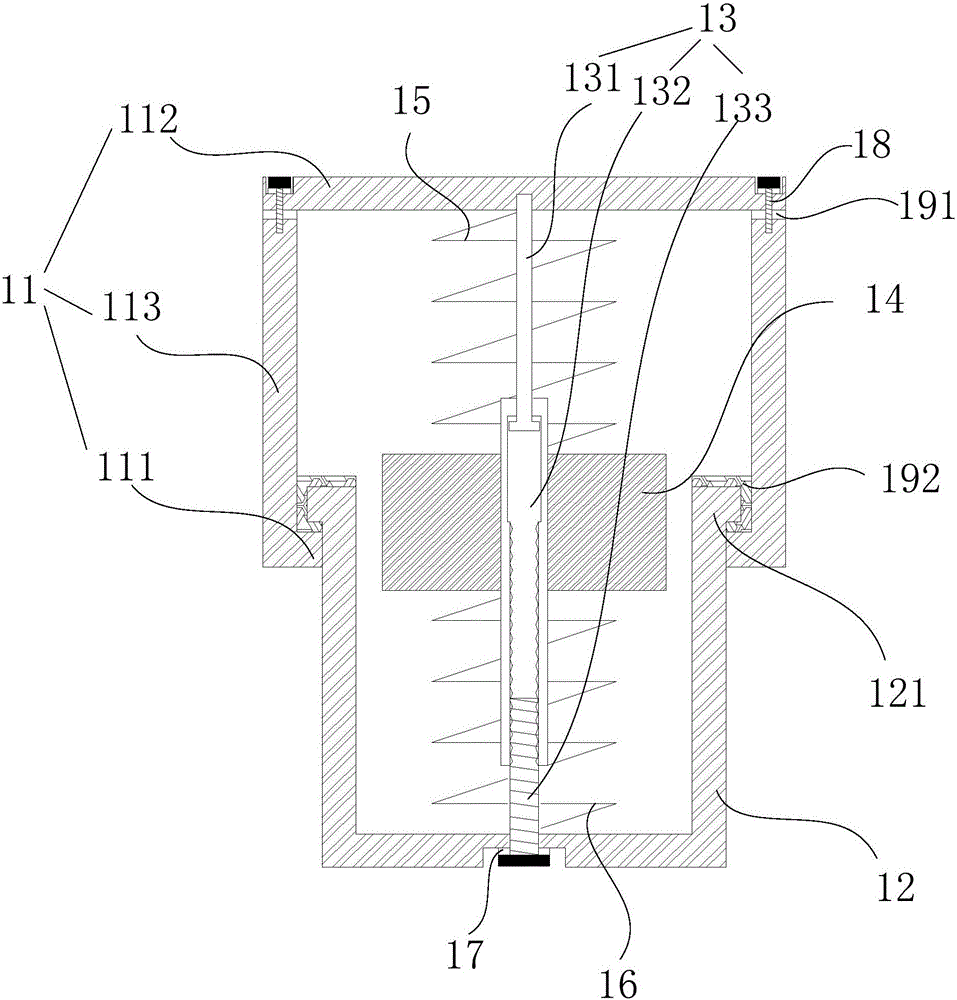
[0047] The embodiment of the present invention provides an energy dissipation vibrator 1, see figure 1 , the energy-dissipating vibrator 1 includes: an upper shell 11, a lower shell 12, a telescopic rod 13, a mass 14, a first spring 15 and a second spring 16;

[0048] The lower end of the upper case 11 is provided with a first blocking portion 111, and the upper end of the lower case 12 is provided with a second blocking portion 121, the second blocking portion 121 is located between the first blocking portion 111 and the upper case 11, and the first blocking portion 111 is The second blocking portion 121 limits the position;

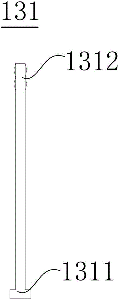
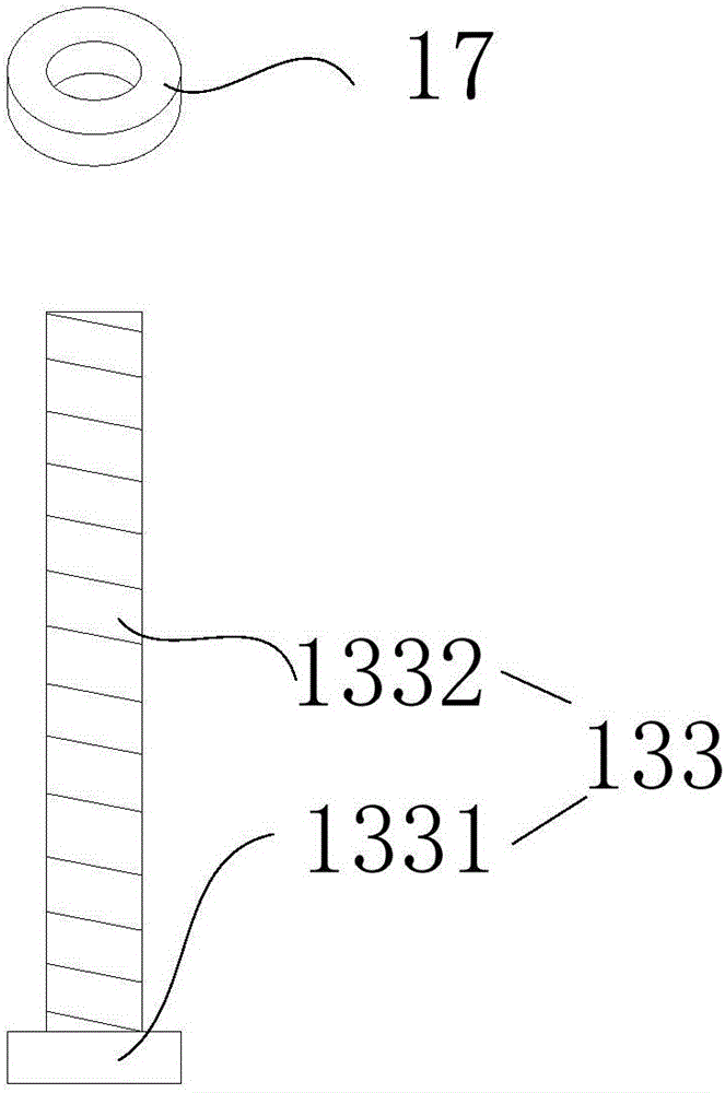
[0049] One end of the telescopic rod 13 is connected to the upper case 11, and the other end is connected to the lower case 12. The mass block 14, the first spring 15 and the second spring 16 are all set on the telescopic rod 13; one end of the first spring 15 is connected to the upper case 11 , the other end is connected to the mass block 14; one end ...

Embodiment 2

[0081] see Figure 10 , the embodiment of the present invention also provides a dynamic protection system in the standing wave area, including a low wave impedance layer 2 and multiple energy-dissipating vibrators 1 described in Embodiment 1;

[0082] The low-wave impedance layer 2 is used to form on the protected underground structure 3, and each energy-dissipating vibrator 1 among the plurality of energy-dissipating vibrators 1 is used to arrange and arrange on the low-wave-impedance layer 2, and the energy-dissipating vibrator 1 is used to support the low-wave impedance layer 2. The rock mass 4 above the acoustic impedance layer 2;

[0083] The upper shell 11 of the energy-dissipating vibrator 1 is connected to the low wave impedance layer 2, and the lower shell 12 is used to connect to the rock mass 4, or

[0084] The lower shell 12 of the energy-dissipating vibrator 1 is connected with the low wave impedance layer 2 , and the upper shell 11 is used for connecting with th...

Embodiment 3

[0089] The embodiment of the present invention also provides a dynamic protection method in the standing wave area, see Figure 10 ,include:

[0090] A low-wave impedance layer 2 is formed on the protected underground structure 3, and a plurality of energy-dissipating vibrators 1 are arranged between the low-wave impedance layer 2 and the rock mass 4;

[0091] Wherein, the upper shell 11 of the energy-dissipating vibrator 1 is connected to the low wave impedance layer 2, and the lower shell 12 is used to connect with the rock mass 4, or

[0092] The lower shell 12 of the energy-dissipating vibrator 1 is connected to the low wave impedance layer 2, and the upper shell 11 is used to connect to the rock mass 4

[0093] The dynamic protection method for the standing wave area adopts the energy-dissipating vibrator 1 described in the first embodiment, so that the dynamic protection method for the standing wave area can better protect the overall stability of the underground struct...


PUM


Abstract

The invention discloses an energy dissipation vibrator and a standing wave area power protecting system and method and belongs to the technical field of underground engineering. The energy dissipation vibrator comprises an upper shell, a lower shell, a telescoping rod, a mass block, a first spring and a second spring. A first blocking part is arranged at the lower end of the upper shell. A second blocking part is arranged at the upper end of the lower shell and located between the first blocking part and the shell. The first blocking part limits the second blocking part. One end of the telescoping rod is connected with the upper shell, and the other end of the telescoping rod is connected with the lower shell. The telescoping rod is sleeved with the mass block, the first spring and the second spring. One end of the first spring is connected with the upper shell, and the other end of the first spring is connected with the mass block. One end of the second spring is connected with the lower shell, and the other end of the second spring is connected with the mass block. The first spring and the second spring are in the compressed state. The energy dissipation vibrator organically combines the traditional antiresonance principle, the deformation energy-absorbing principle and the standing wave principle together, and integrates and has multiple advantages of various single principles.

Description

technical field [0001] The invention relates to the technical field of underground engineering, in particular to an energy dissipation vibrator and a dynamic protection system and method for a standing wave area. Background technique [0002] Under the background of the country's vigorous construction of underground projects such as subways, highway tunnels, and underground expressways, it is necessary to study the dynamic protection issues such as seismic / explosion resistance of underground projects. [0003] The current anti-seismic / anti-explosion technology of underground engineering mainly optimizes the design from two aspects of structure and material. Structure-based anti-seismic / anti-explosion technology is mainly realized by adopting structural forms that are conducive to stress wave reflection, diffraction and scattering, such as circular structures, arch structures, structures with structural holes, and multi-layer composite structures. Material-based dynamic prot...

Claims


Application Information

Patent Timeline
Patent Type & Authority Applications(China)
IPC IPC(8): E02D31/08
CPCE02D31/08
Inventor 刘元雪张裕吴润泽谭仪忠赵吉昌胡明李争任建波宋林波高玉龙
Owner 刘元雪
Why Eureka
Try Eureka