
Underground pipe gallery construction device, combination and construction method

A technology of integrated pipe gallery and construction device, which is applied in earth-moving drilling, mining equipment, tunnels, etc., can solve the problems that the integrated pipe gallery is not very suitable, the traffic in the old city is difficult, and the road surface is damaged, and the construction speed is fast and the quality is reliable. , the effect of high safety

Inactive Publication Date: 2016-08-24
JIANGSU HONGJI ENERGY SAVING NEW TECH CO LTD
View PDF12 Cites 16 Cited by
  • Summary
  • Abstract
  • Description
  • Claims
  • Application Information

AI Technical Summary

Benefits of technology

This new technology solves problems such as damaging roads or causing interruptions during transportations by creating an improved structure that overcomes these issues without requiring expensive repairs on existing infrastructure. It also allows for quicker assembly times while maintaining its strength against external forces like winds. Additionally, this design makes installation easier because it does away with any unnecessary parts needed after placement instead of rebuilding them afterwards. Overall, this innovative solution improves efficiency and reduces costs compared to previous methods.

Problems solved by technology

This technical problem addressed by this patented technology relates to constructing an efficient way to protect underground pipes during excavations or other activities such as tunneling operations without causing damage on existing infrastructure like roads or buildings due to overexcitation caused by environmental factors like water intrusions or pollution.

Method used


Image

  • Underground pipe gallery construction device, combination and construction method
  • Underground pipe gallery construction device, combination and construction method
  • Underground pipe gallery construction device, combination and construction method

Examples


Embodiment Construction

[0030] The technical solutions of the present invention will be described in further detail below in conjunction with the accompanying drawings and embodiments.

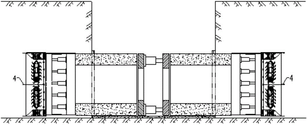
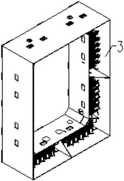
[0031] In the construction device of the underground comprehensive pipe gallery of the present invention, the section of the corresponding pipe gallery is square, circular or polygonal, and a plurality of mixing heads 1 are arranged according to the cross-sectional shape of the front end of the prefabricated pipe gallery, and are fixed on the front end of the propeller 2 of the stirring head, The rear end of the mixing head propeller 2 is connected with the prefabricated pipe gallery. An embodiment of the construction device of the present invention includes: a stirring head thruster 2 arranged at one end of the prefabricated pipe gallery, a plurality of stirring heads 1 fixedly installed at the front end of the stirring head thruster 2, and a mixing head 1 arranged at the other end of the prefabricated pipe gallery ...


PUM


Abstract

The invention discloses an underground pipe gallery construction device, a combination and a method. The device comprises a stirring head thruster arranged at one end of a prefabricated pipe gallery, multiple stirring heads fixedly mounted at the front end of the stirring head thruster, a pipe gallery jacking component arranged at the other end of the prefabricated pipe gallery and a jack connected with the pipe gallery jacking component, wherein the stirring head thruster and the stirring heads are arranged along the cross section of the prefabricated pipe gallery; and a separation anti-interference cover formed by steel plates is arranged around the outer side of the front end of the stirring head. The device has the advantages of cost reduction, fast construction and reliable quality.

Description


Claims


Application Information

Patent Timeline
Owner JIANGSU HONGJI ENERGY SAVING NEW TECH CO LTD
Learn More