
Urea mixing device

A technology of mixing device and urea, which is applied in muffler device, exhaust device, exhaust gas treatment and other directions, can solve the problems of insufficient decomposition and atomization of urea, low SCR conversion efficiency, poor mixing uniformity of urea and exhaust gas, etc. Risk of crystallization, effect of improving transformation efficiency

Active Publication Date: 2016-08-24
WEICHAI POWER CO LTD
View PDF4 Cites 6 Cited by
  • Summary
  • Abstract
  • Description
  • Claims
  • Application Information

AI Technical Summary

Problems solved by technology

[0005] The technical problem to be solved by the present invention is how to solve the technical problems of insufficient urea decomposition and atomization, poor mixing uniformity of urea and exhaust gas, and low SCR conversion efficiency

Method used


Image

  • Urea mixing device
  • Urea mixing device

Examples


Embodiment Construction

[0019] The specific implementation manners of the present invention will be further described in detail below in conjunction with the accompanying drawings and embodiments. The following examples are used to illustrate the present invention, but are not intended to limit the scope of the present invention.

[0020] In the description of the present invention, it should be noted that the terms "center", "longitudinal", "transverse", "upper", "lower", "front", "rear", "left", "right", " The orientations or positional relationships indicated by "vertical", "horizontal", "top", "bottom", "inner", "outer", etc. are based on the orientation or positional relationships shown in the drawings, and are only for the convenience of describing the present invention and simplifying Describes, but does not indicate or imply that the device or element referred to must have a specific orientation, be constructed in a specific orientation, and operate in a specific orientation, and therefore sh...


PUM


Abstract

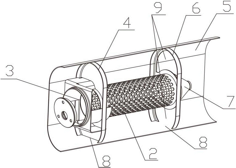
The invention discloses a urea mixing device. The urea mixing device comprises a swirler, a porous tube, an opening necked tube and a mixing outer tube, wherein the swirler communicates with one end of the porous tube; the swirler and the porous tube are arranged inside the mixing outer tube; the periphery of the swirler fits the inner wall of the mixing outer tube; a cavity is formed between the porous tube and the inner wall of the mixing outer tube; a plurality of through holes are formed in the tube wall of the porous tube; the other end of the porous tube is connected with the opening necked tube; and the diameter of the opening necked tube is gradually smaller from the end connected with the porous tube to the exterior. According to the urea mixing device, the technical problems that urea is not fully decomposed and atomized, the mixing uniformity of urea and waste gas is poor, and the SCR conversion efficiency is low can be solved.

Description

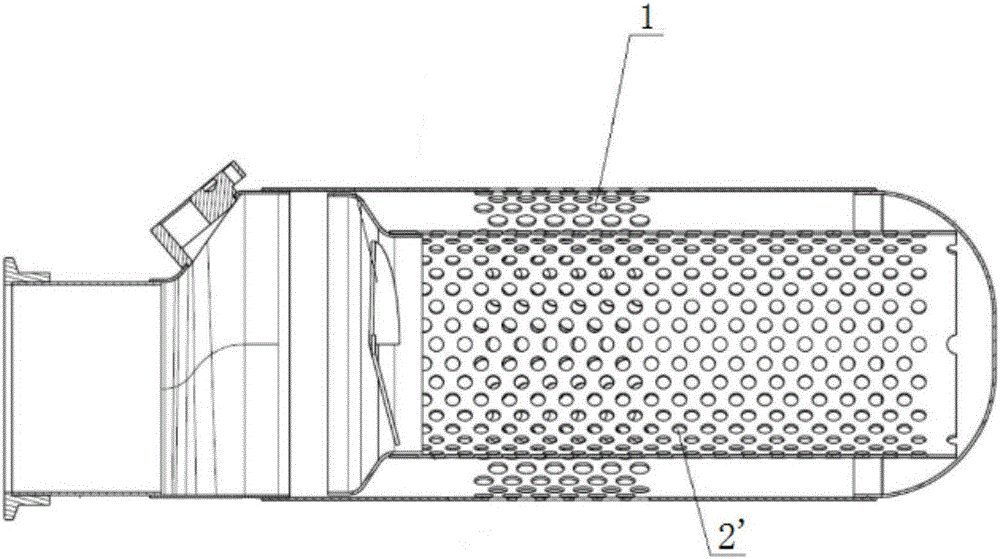
technical field [0001] The invention relates to the field of tail gas treatment, in particular to a urea mixing device. Background technique [0002] figure 1 It is an existing porous tube mixing device, which adopts a double-layer structure with an outer porous tube 1 and an inner porous tube 2'. After the air flow enters the mixing device, it drives the flow of urea sprayed from the urea nozzle. After the action of the double-layer porous tube, the air flow passes through Through the holes on the inner porous pipe 2' and the outer porous pipe 1, the urea is broken up and then atomized and decomposed. [0003] However, the porous tube mixing device can only rely on the air flow to drive the urea through the internal and external porous tubes to break up the urea. The porous pipe 2' in this mixing device has a large diameter, low flow energy of the airflow, unable to fully disperse the urea, insufficient decomposition and atomization of the urea, poor mixing uniformity of ...

Claims


Application Information

Patent Timeline
Patent Type & Authority Applications(China)
IPC IPC(8): F01N3/20
CPCF01N3/2073F01N2610/02Y02T10/12
Inventor 王东升陶建忠王意宝张晓丽魏星
Owner WEICHAI POWER CO LTD
Learn More