Paint spraying room with double atomizing paint mist catching structure

A paint spray booth and paint mist technology, applied in the field of paint spray booths, can solve the problems of small surface area, large load and low capture rate of the water curtain, and achieve the effect of simplifying the support structure and manufacturing difficulty.

Inactive Publication Date: 2015-03-11
赛智环保科技(天津)有限公司
View PDF5 Cites 8 Cited by
  • Summary
  • Abstract
  • Description
  • Claims
  • Application Information

AI Technical Summary

Problems solved by technology

[0002] Spraying is an important process step in industrial production. It is involved in industries such as automobiles, furniture, and packaging. Spraying is generally carried out in a spray booth. Capture, to realize the separation of VOC and paint mist, so as to carry out effective environmental protection treatment respectively. The structure used to capture paint mist in the existing spray booth is mainly through the vertical water curtain plate, and the water curtain is formed on the surface of the vertical water curtain plate to capture the spray paint. Excessive paint mist, but the structure has limited capture capacity and low capture rate. The reason is that the surface area forming the water curtain is small, and the capture rate is relatively low on the limited water curtain plate. Since the paint mist is carried out by the gas, it is Subsequent environmental protection treatment of organic waste gas has a large load

Method used


Image

  • Paint spraying room with double atomizing paint mist catching structure
  • Paint spraying room with double atomizing paint mist catching structure
  • Paint spraying room with double atomizing paint mist catching structure

Examples


Embodiment Construction

[0026] The present invention will be further described in detail below through the specific examples, the following examples are only descriptive, not restrictive, and cannot limit the protection scope of the present invention with this.

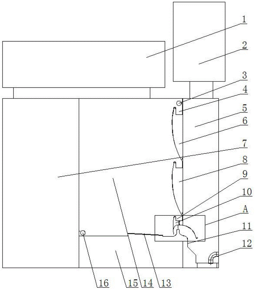
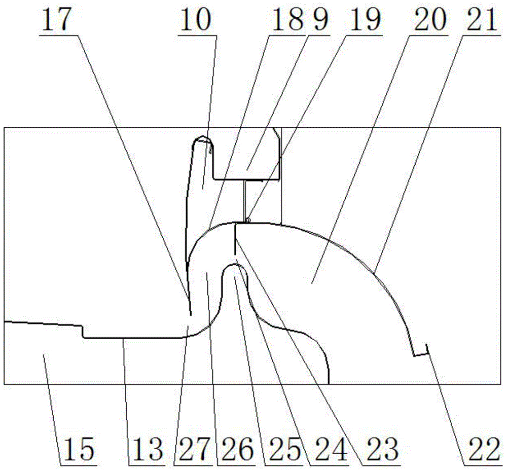
[0027] A spray booth with a double atomized paint mist capture structure, comprising a spray booth 14, a personnel operation room 7 is set on one side of the spray booth, and a steam-water separation room 5 is set on the other side of the spray booth. The air blower 1 is installed above, the induced draft fan 2 is installed above the steam-water separation room, the water curtain plate is installed on the wall of the spray room, and the gutter water supply pipe 3 is installed above the water curtain plate in the spray room.

[0028] The water curtain plate includes a first-stage water curtain plate 6, a second-stage water curtain plate 8, and a third-stage water curtain plate 10 arranged in sequence from top to bottom, and it also includes a ...


PUM


Abstract

The invention relates to a paint spraying room with a double atomizing paint mist catching structure. The paint spraying room comprises a paint spraying room body. A water screen plate is installed on the wall of the paint spraying room body. The paint spraying room further comprises a base plate flow guide structure and a main sawtooth plate which are arranged below the paint spraying room. The water screen plate is arranged above the base plate flow guide structure. The main sawtooth plate is fixedly installed at the bottom end of the water screen plate, an arc lifting section is manufactured at the bottom end of the water screen plate, a flow guide sawtooth plate is installed on the lateral wall of the water screen plate at the upper end of the arc lifting section, the flow guide sawtooth plate integrally extends to form the arc flow guide face, the arc flow guide face is matched with the base plate flow guide structure, a first vortex atmozing space is formed among the main sawtooth plate, the flow guide sawtooth plate, the arc lifting section at the bottom end of the water screen plate and the base plate flow guide structure, and a second vortex atomizing space is formed between the flow guide sawtooth plate and the base plate flow guide structure. The paint spraying room is simple in structure, scientific and reasonable in design, low in cost, high in paint mist catching efficiency and capable of effectively reducing the follow-up environment protection processing load.

Description

technical field [0001] The invention belongs to the field of painting booths, in particular to a painting booth with a structure for capturing double atomized paint mist. Background technique [0002] Spraying is an important process step in industrial production. It is involved in industries such as automobiles, furniture, and packaging. Spraying is generally carried out in a spray booth. Capture, to realize the separation of VOC and paint mist, so as to carry out effective environmental protection treatment respectively. The structure used to capture paint mist in the existing spray booth is mainly through the vertical water curtain plate, and the water curtain is formed on the surface of the vertical water curtain plate to capture the spray paint. Excessive paint mist, but the structure has limited capture capacity and low capture rate. The reason is that the surface area forming the water curtain is small, and the capture rate is relatively low on the limited water curta...

Claims


Application Information

Patent Timeline
Patent Type & Authority Applications(China)
IPC IPC(8): B05B15/12B05B15/04
CPCB05B14/40B05B14/465
Inventor 朱殿兴冯正刘光明谷德明赵崇光
Owner 赛智环保科技(天津)有限公司
Why Eureka
Try Eureka