Amorphous Alloy Composite Iron Core Electromagnetic Control Injector

An amorphous alloy, electromagnetic control technology, used in machines/engines, fuel injection devices, engine components, etc., can solve the problems of reducing long-term operating life, energy waste, shortening the life of electronically controlled injectors, etc., to improve long-term operation. The effect of life, core loss reduction, and valve stem movement response speeding up

Active Publication Date: 2018-05-18
HARBIN ENG UNIV
View PDF8 Cites 0 Cited by
  • Summary
  • Abstract
  • Description
  • Claims
  • Application Information

AI Technical Summary

Problems solved by technology

These losses often exist in the form of heat energy after formation. On the one hand, it is a waste of energy. On the other hand, it will gradually increase the working temperature of the high-speed electromagnet assembly and reduce its long-term operating life. The shortening of the life of the high-speed electromagnet assembly will make the entire Shortened life of electronically controlled injectors

Method used


Image

  • Amorphous Alloy Composite Iron Core Electromagnetic Control Injector
  • Amorphous Alloy Composite Iron Core Electromagnetic Control Injector
  • Amorphous Alloy Composite Iron Core Electromagnetic Control Injector

Examples


Embodiment approach 1

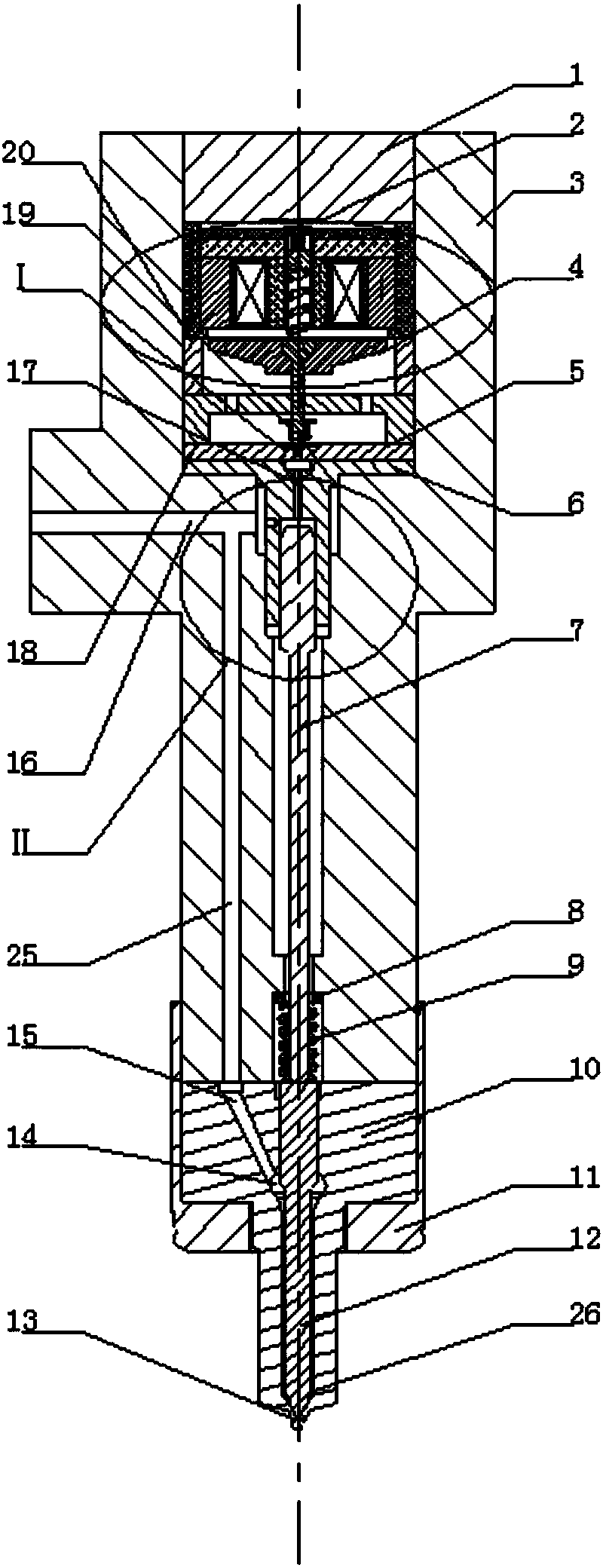
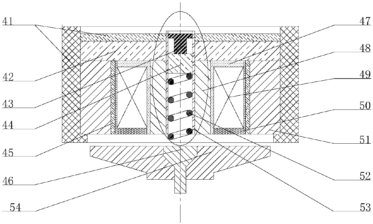
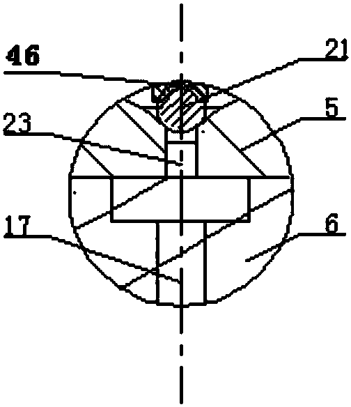
[0024] combine figure 1 -7. The composition of this embodiment includes injector head fastening nut 1, amorphous alloy electromagnet assembly 2, injector body 3, electromagnet assembly chamber 4, pilot ball valve seat 5, control piston body 6, needle valve Push rod 7, needle valve return spring seat 8, needle valve return spring 9, nozzle 10, nozzle fastening nut 11, needle valve 12, dividing plate 18, stop ring 19, cushion block 20 these components. The needle valve ejector rod 7 and the control piston body 6 are sequentially installed from the upper part of the injector body 3, and the amorphous alloy electromagnet assembly 2, the electromagnetic pilot ball valve, the partition plate 18, the stop ring 19, the cushion block 20 and the pilot ball valve seat 5 After being assembled together in a reasonable order, they are finally placed on the control piston body 6, and are fixed by the uppermost injector head fastening nut 1, and the needle valve return spring 9 is combined wi...

Embodiment approach 2

[0028] This embodiment is to change the structural combination of the flange extending from the lower part of the casing 41 of the amorphous alloy electromagnet assembly 2 in the first embodiment 2 along the side near the coil, and the flange is changed from a complete ring flange to an equal ring flange. The evenly spaced circular arc flanges also play a role in fixing the amorphous alloy electromagnet assembly, which can save flange materials and relatively increase the bond between the composite iron core and the lower temperature fuel in the amorphous alloy electromagnet assembly. contact area to enhance heat dissipation.


PUM


Abstract

The invention aims to provide an amorphous alloy electromagnetic control oil injector with a combined iron core. An amorphous alloy electromagnet assembly, a pilot ball valve seat, a control piston body and a needle valve ejector rod are installed in an oil injector body in sequence from top to bottom, a nozzle is fixedly arranged at the bottom of the oil injector body through a nozzle clamp nut, and a needle valve is installed in the nozzle. Compared with a conventional silicon steel sheet magnetic pole, the amorphous alloy electromagnetic control oil injector with the combined iron core has the advantage that the loss of the iron core is greatly reduced. In addition, due to the facts that a copper ring is arranged between an auxiliary magnetic pole and coils in the amorphous alloy electromagnet assembly, copper has good electrical conductivity, and the constantly-enhanced magnetic field can generate high induced current in the copper ring to delay the increase of the magnetic flux, the effective inductance of the coils in the working process is greatly reduced, the increase speed of the driving current of the coils is increased, the movement response of a valve rod is quickened, the response speed of the amorphous alloy electromagnetic control oil injector with the combined iron core can be conveniently increased, and the loss is reduced.

Description

technical field [0001] The invention relates to a fuel injector, specifically a diesel fuel injector. Background technique [0002] With the development of society and the advancement of science and technology, the diesel engine industry is facing more and more pressure from energy and environmental issues. Diesel engines must adopt corresponding solutions to improve the performance of diesel engines, improve the economy and emissions of diesel engines, etc. Diesel engines The electronically controlled fuel system has become a necessary measure to improve the performance of the diesel engine because of its good characteristics such as high injection pressure, high control precision, and high control freedom. As an important executive component of the electronically controlled fuel system, the electronically controlled fuel injector itself has The response speed of the electronically controlled fuel injector greatly affects the fuel injection rate of the electronically contro...

Claims


Application Information

Patent Timeline
Patent Type & Authority Patents(China)
IPC IPC(8): F02M51/06F02M61/10
CPCF02M51/06F02M61/10
Inventor 范立云刘鹏彭文博马修真宋恩哲
Owner HARBIN ENG UNIV
Why Eureka
Try Eureka