
System And Method For Controlling Forward/Reverse Rotation Of Fan

A control system and fan technology, applied in pump control, components of pumping devices for elastic fluids, non-variable pumps, etc., can solve problems such as dust accumulation on fan blades that cannot be effectively solved

Active Publication Date: 2016-08-24
DELTA ELECTRONICS INC
View PDF9 Cites 14 Cited by
  • Summary
  • Abstract
  • Description
  • Claims
  • Application Information

AI Technical Summary

Problems solved by technology

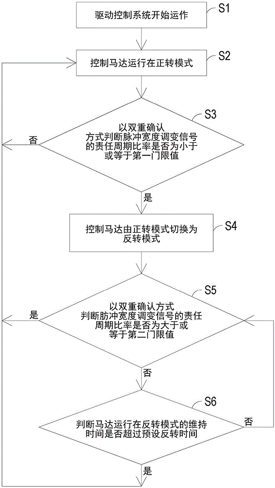
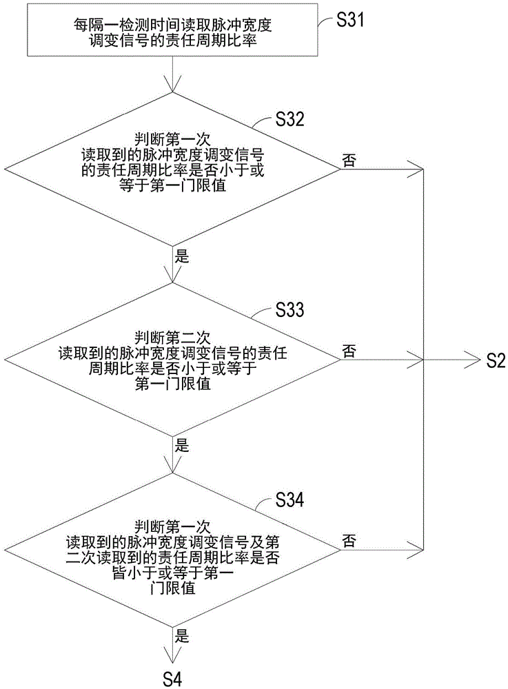
[0008] The main purpose of this case is to provide a control system for controlling the forward and reverse rotation of the fan and its applicable control method. The corresponding control motor executes the forward rotation mode or the reverse rotation mode to solve the problem that the existing fan control system cannot effectively solve the dust accumulation on the fan blades of the fan, and it is easy to misjudge that the fan needs to switch between forward rotation and reverse rotation. Defects such as wrong control

Method used


Image

  • System And Method For Controlling Forward/Reverse Rotation Of Fan
  • System And Method For Controlling Forward/Reverse Rotation Of Fan
  • System And Method For Controlling Forward/Reverse Rotation Of Fan

Examples


Embodiment Construction

[0040] Some typical embodiments embodying the features and advantages of the present application will be described in detail in the description in the following paragraphs. It should be understood that the present application can have various changes in different aspects without departing from the scope of the present application, and the description and drawings therein are used for illustration in nature rather than limiting the present application.

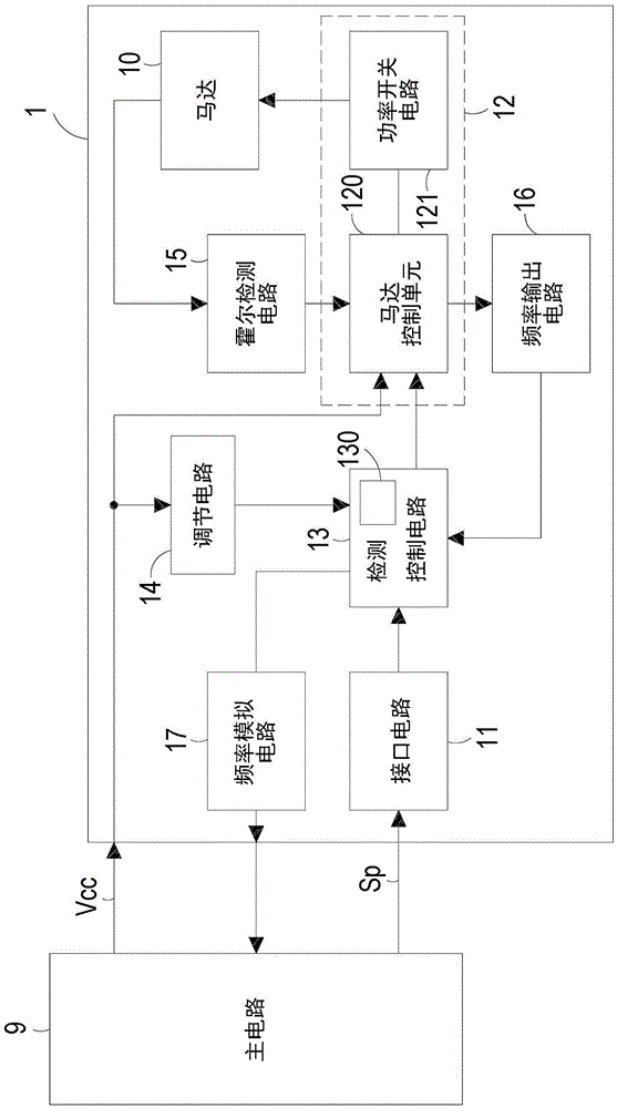
[0041] Please also see figure 1 , which is a schematic block diagram of the circuit structure of the control system for controlling the forward and reverse rotation of the fan in a preferred embodiment of the present application. Such as figure 1 As shown, the control system 1 of this embodiment is used to control a fan (not shown) in an electronic device to perform forward rotation to dissipate heat or reverse rotation to remove dust. The electronic device has a main circuit 9, which is electrically connected to the control ...


PUM


Abstract

The invention provides a system and method for controlling forward / reverse rotation of fan. The control system includes a motor, an interface circuit, a motor controller and a detection control circuit. The interface circuit receives and converts a pulse width modulation signal. The fan dissipates heat when the motor is operated in a forward rotation mode and eliminates dust when the motor is operated in a reverse rotation mode. The detection control circuit reads a duty cycle of the converted pulse width modulation signal in real time. When the motor is operated in the forward rotation mode, the detection control circuit drives the motor controller to control the rotation speed of the fan according to the duty cycle. If the duty cycle is lower than or equal to a first threshold value, the detection control circuit drives the motor controller to switch operation mode of the motor from the forward rotation mode to the reverse rotation mode. The control system can dynamically control the motor and the fan to carry out forward rotation for blowing and reverse rotation for ventilation, in order to realize radiation and dust removal purposes with high efficiency.

Description

technical field [0001] This case involves a control system, especially a control system for controlling the forward and reverse rotation of a fan and its applicable control method. Background technique [0002] The fan used for heat dissipation is a very important heat dissipation structure for electronic equipment, because the temperature will directly affect the operating performance, stability and service life of electronic components, and the structural design of the fan is also related to the type of electronic equipment. Changes with design trends. [0003] The design orientation of the fan installed in the electronic equipment is mainly to provide heat dissipation function, and the purpose is not to affect the normal operation of the electronic equipment. The fan sucks the air into the body through the air inlet of the electronic equipment, and then passes the air with heat energy through the electronic equipment. The air outlet of the equipment is exhausted, thereby...

Claims


Application Information

Patent Timeline
IPC IPC(8): F04D27/00F04D29/70
CPCF04D27/00F04D27/004F04D27/007F04D29/701
Inventor 刘政杰苏锦平苏德胜王文志
Owner DELTA ELECTRONICS INC
Learn More