Static contact structure of disk-shaped non-excitation tap switch

A technology of tap changer and static contact, which is applied in the direction of electric switches, electrical components, circuits, etc., can solve the problems of large width, increased volume, weight and cost of transformers, and reduced insulation reliability, so as to reduce bending radius, Reduce tip discharge and improve the effect of electric field

Active Publication Date: 2016-08-24
WUHAN TAIPU TRANSFORMER CHANGER
View PDF7 Cites 2 Cited by
  • Summary
  • Abstract
  • Description
  • Claims
  • Application Information

AI Technical Summary

Problems solved by technology

[0002] In the Chinese patent CN01212470.2, a non-excitation tap changer is disclosed. Its columnar static contacts extend radially out of the switch base and are in the shape of annular rays. There are holes inside the static contacts for connecting with the transformer coil. Lead wires are connected, since the transformer lead wires coming from the high-voltage side of the transformer must have a certain bending radius when connecting with each static contact, this will cause the width of the connecting lead wires of the disc-shaped off-excitation tap-changer to be relatively large, and for smaller capacity For the transformer, it will be closer to other parts of the transformer (such as the bushing and its tail), other leads and the box wall, so that the insulation reliability will be reduced, and sometimes the width or even the height of the oil tank has to be widened, resulting in the volume and weight of the transformer. and cost increase

Method used


Image

  • Static contact structure of disk-shaped non-excitation tap switch
  • Static contact structure of disk-shaped non-excitation tap switch
  • Static contact structure of disk-shaped non-excitation tap switch

Examples


Embodiment Construction

[0022] The present invention will be further described below in conjunction with accompanying drawing.

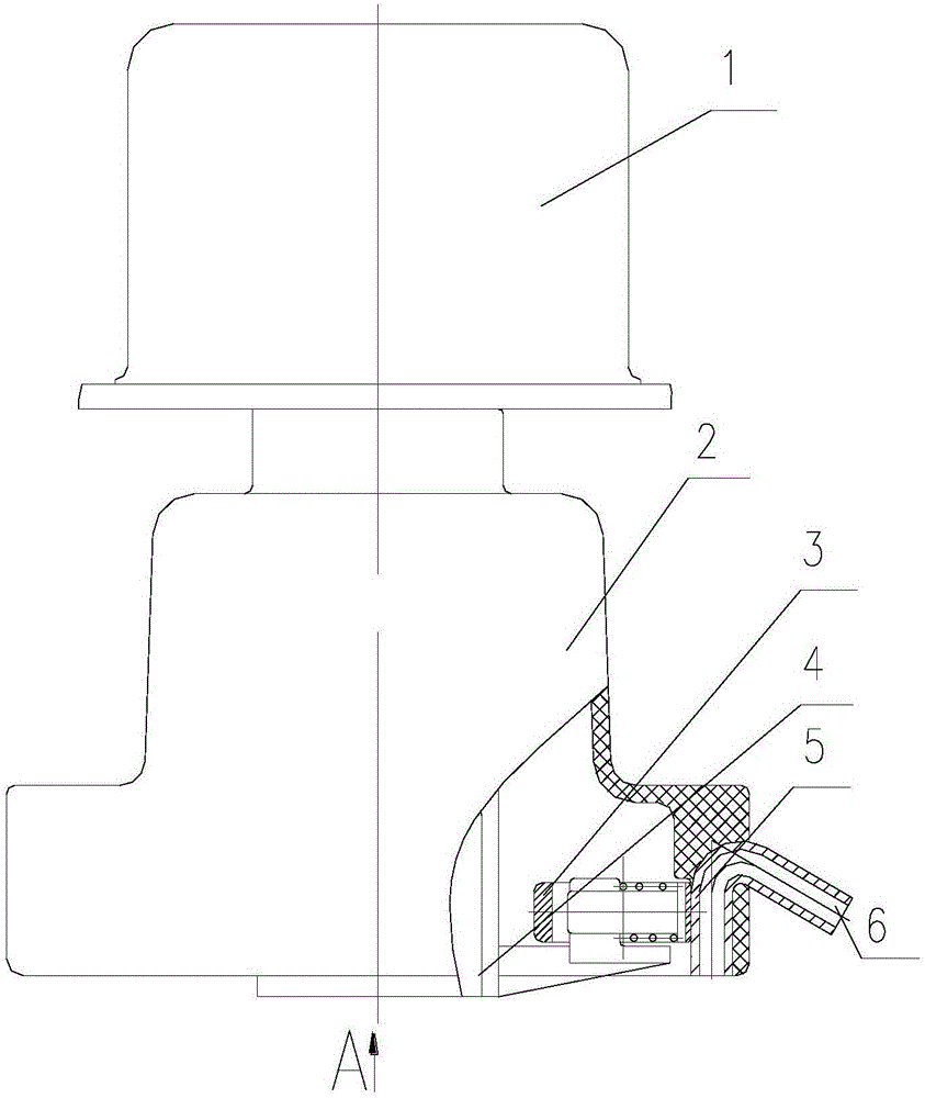
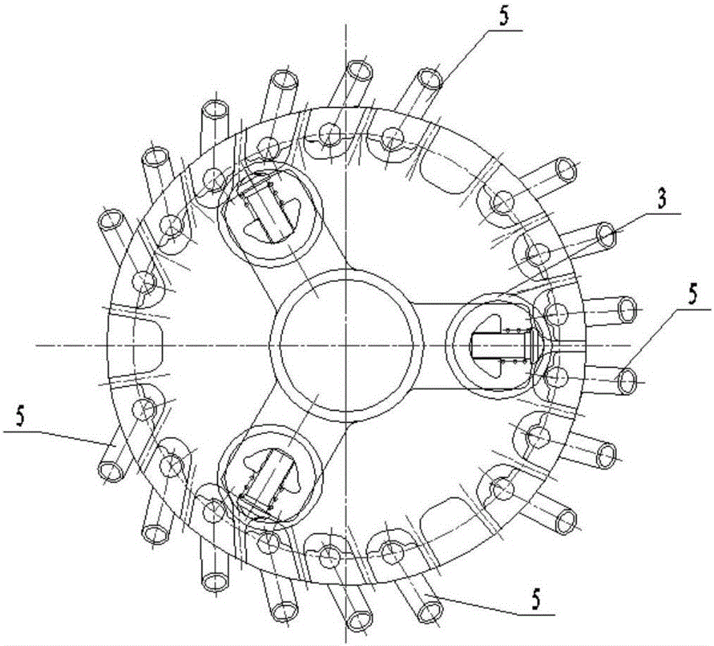
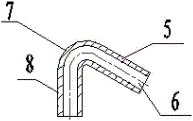
[0023] Such as Figure 1-2 As shown, this embodiment provides a static contact structure of a three-phase disc-shaped off-excitation tap changer, including a switch base 2 and a rotating shaft 4 mounted on the switch base. The upper end of the rotating shaft 4 is connected to the operating positioning device 1, and the rotating shaft The lower end of 4 is equipped with radial elastic rolling contact 3, and the corresponding radial elastic rolling contact 3 on the switch base is arranged with 3 phase static contacts at circumferential intervals, and each phase static contact is composed of multiple static contacts. The static contact includes a columnar static contact body 8 and a connection terminal 5. The static contact body 8 extends into the inner cavity of the switch seat and is configured with the radial elastic rolling contact 3. The static contact body 8 The upper e...


PUM


Abstract

The invention discloses a static contact structure of a disk-shaped non-excitation tap switch. The static contact structure comprises a switch base and a rotary shaft which is arranged on the switch base in a penetration manner, wherein the upper end of the rotary shaft is connected with an operating and positioning apparatus while a radially and elastically rolled moving contact is mounted at the lower end of the rotary shaft; static contacts are distributed, corresponding to the circumferential direction of the radially and elastically rolled moving contact, on the switch base at intervals; each static contact comprises a columnar static contact body and a cylindrical terminal connected with the corresponding static contact body; the static contact bodies are matched with the radially and elastically rolled moving contact; the upper ends of the static contact bodies are bent downwards to form the terminals; and the terminals extend out of the switch base. According to the static contact structure provided by the invention, the terminals are bent downwards, so that the axial length of the whole static contacts along the direction of the switch base can be the minimum, and the height of the switch is lowered; and in addition, an annular electrode is arranged over the ground, so that the electric field is uniform, and the insulating performance of the static contact structure is improved.

Description

technical field [0001] The invention relates to a static contact structure of a disc-shaped off-excitation tap changer. Background technique [0002] In the Chinese patent CN01212470.2, a non-excitation tap changer is disclosed. Its columnar static contacts are distributed radially out of the switch base and are in the shape of annular rays. There are holes inside the static contacts for connecting with the transformer coil. Lead wires are connected, since the transformer lead wires coming from the high-voltage side of the transformer must have a certain bending radius when connecting with each static contact, this will cause the width of the connecting lead wires of the disc-shaped off-excitation tap-changer to be relatively large, and for smaller capacity For the transformer, it will be closer to other parts of the transformer (such as the bushing and its tail), other leads and the box wall, so that the insulation reliability will be reduced, and sometimes the width or eve...

Claims


Application Information

Patent Timeline
Patent Type & Authority Applications(China)
IPC IPC(8): H01H9/00
CPCH01H9/0016
Inventor 丁志彪刘刚
Owner WUHAN TAIPU TRANSFORMER CHANGER
Why Eureka
Try Eureka