Pneumatic vertical line pressing device and line pressing method thereof

A wire crimping device and vertical technology, applied in the field of pneumatic vertical wire crimping devices, can solve the problems of easily crushing the core wire sheath, the core wire copper wire being easily damaged, the core wire being broken, etc.

Active Publication Date: 2016-08-24
SHENZHEN YALISHENG TECH CO LTD
View PDF5 Cites 6 Cited by
  • Summary
  • Abstract
  • Description
  • Claims
  • Application Information

AI Technical Summary

Problems solved by technology

[0003] 1) Manually using tweezers to clamp the wire, it is easy to break the core wire (the copper wire of the core wire is easily damaged);
[0004] 2) The 45º crimping handle is used to crimp the wire, which is easy to crush the core wire and the sheath

Method used


Image

  • Pneumatic vertical line pressing device and line pressing method thereof
  • Pneumatic vertical line pressing device and line pressing method thereof
  • Pneumatic vertical line pressing device and line pressing method thereof

Examples


Embodiment Construction

[0038] In order to express the present invention more clearly, the present invention will be further described below in conjunction with the accompanying drawings.

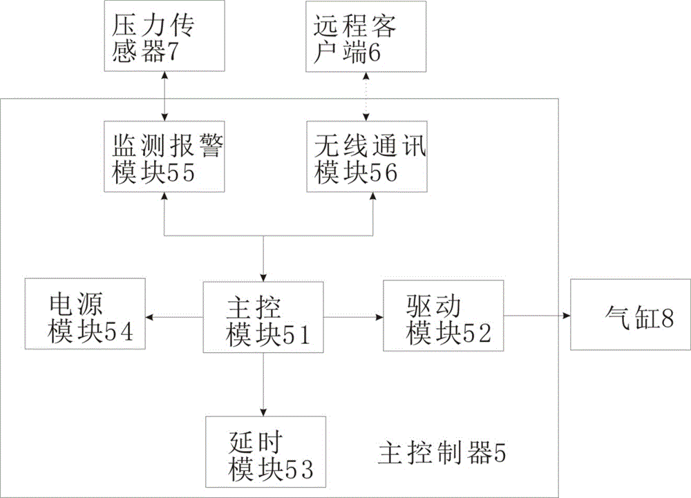
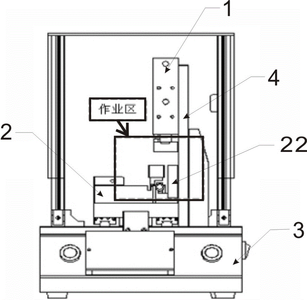
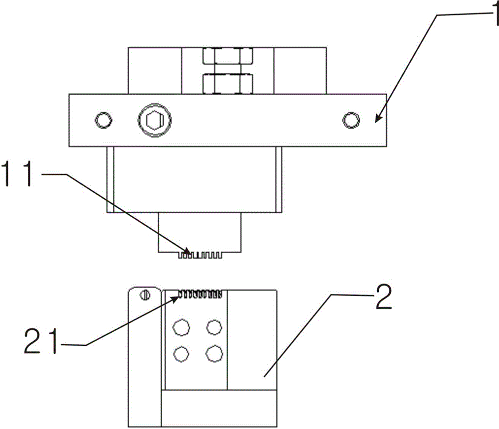
[0039] see Figure 1-Figure 4 , a pneumatic vertical crimping device provided by the present invention includes an upper module 1, a lower module 2 and a base 3, the lower module 2 is fixed on the base 3, a bracket 4 is arranged on one side of the lower module 2, and a bracket 4 is arranged on the There is a cylinder 8, the upper module 1 is fixed on the bracket 4, the cylinder is connected with the upper module 1, the upper module 1 moves up and down under the control of the cylinder 8, the lower module 2 is just at the upper end of the upper module 1, and the base 3 is also provided with The main controller 5, the lower module 2 is provided with a first guide groove 21, the upper module 1 is provided with a second guide groove 11, and a wire clip (not shown) is installed in the first guide groove 21, when the up...


PUM


Abstract

The invention discloses a pneumatic vertical line pressing device and a line pressing method thereof. The pneumatic vertical line pressing device comprises an upper module, a lower module and a base, wherein the lower module is fixed on the base; a bracket is arranged at one side of the lower module; the upper module is movably fixed on the bracket; the lower module is just located at the upper end of the upper module; and the base is also provided with a master controller. First guide grooves are formed in the lower module; and second lead wire grooves are formed in the upper module, so that the direction of a to-be-pressed line can be well controlled; and the risk that a copper wire in the to-be-pressed line is snapped off during operation employing tweezers is avoided. Meanwhile, the lower module is arranged at the lower end of the upper module, namely the lower module and the upper module are in a 90-degree up-and-down vertical operation manner; and an alarm module is arranged, so that the risks that a hand of an operator is crushed and the to-be-pressed line is crushed when pressed into a wire clamp since the upper module and an air cylinder touch a switch during the operation of the operator are avoided. Meanwhile, a time delay module is arranged, so that the condition that the line is pulled up when the upper module and the lower module of a jig move too fast is avoided.

Description

technical field [0001] The invention relates to the field of mechanical fixtures, in particular to a pneumatic vertical crimping device and a crimping method thereof. Background technique [0002] Fixtures are a large class of tools for woodworking, ironwork, fitter, machinery, electric control and other handicrafts, mainly as a tool to assist in controlling position or movement (or both). With the popularity of high-definition LCD TVs, the demand for HDMI cable harnesses is increasing. The traditional way of HDMI wiring is to hold the line card with tweezers to work or put the line card into the jig, and then use the tweezers to wrap the core. The wire is clamped to the clamp, and the core wire is pressed into the slot with a 45º crimping handle. The above two methods have the following defects: [0003] 1) Manually using tweezers to clamp the wire, it is easy to break the core wire (the copper wire of the core wire is easily damaged); [0004] 2) The 45º crimping handle ...

Claims


Application Information

Patent Timeline
Patent Type & Authority Applications(China)
IPC IPC(8): H01R43/048
CPCH01R43/048
Inventor 林松根李发红刘桂宝
Owner SHENZHEN YALISHENG TECH CO LTD
Why Eureka
Try Eureka