
Intelligent combination control system and redundancy judgment method for electric power terminal power factor

A power factor, power terminal technology, applied in reactive power adjustment/elimination/compensation, electrical components, reactive power compensation and other directions, can solve problems such as system voltage fluctuation, unstable switching, affecting power supply quality, etc.

Inactive Publication Date: 2016-08-24
吕世全
View PDF4 Cites 11 Cited by
  • Summary
  • Abstract
  • Description
  • Claims
  • Application Information

AI Technical Summary

Problems solved by technology

Disadvantages of the system 1: Frequent switching and over-compensation and under-compensation are unstable, causing system voltage fluctuations to affect the quality of power supply; 2: High failure rate, often unable to be put into operation due to failures. If the power factor is lower than 0.9, the power supply department will increase the power adjustment electricity fee in the power rate assessment column, as the saying goes; 3: Frequent over-compensation causes power loss and wastes power
[0004] The voltage fluctuation of the original operating system affects the quality of power supply, so over-compensation wastes electric energy. After the under-compensation, the power supply department will automatically check the power factor of the user every month. If the power factor is lower than 0.9, the power adjustment fee will be imposed. If the power factor is stable at 0.98, the power supply department will give Reduction of power adjustment fees, rewards and punishments, often due to failures that cannot be put into normal operation, the power factor is lower than the specified value, and because the power factor cannot reach 0.9 or more, the power supply department will increase the power adjustment fee in the power rate assessment column, as the saying goes, a fine
[0005] However, the above measures cannot change the high power factor from the technical level and fundamentally.

Method used


Image

  • Intelligent combination control system and redundancy judgment method for electric power terminal power factor
  • Intelligent combination control system and redundancy judgment method for electric power terminal power factor
  • Intelligent combination control system and redundancy judgment method for electric power terminal power factor

Examples


Embodiment Construction

[0040] The following will clearly and completely describe the technical solutions in the embodiments of the present invention with reference to the accompanying drawings in the embodiments of the present invention. Obviously, the described embodiments are only some, not all, embodiments of the present invention.

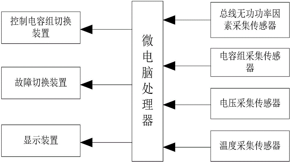
[0041] see figure 1 As shown, it is a schematic structural diagram of an intelligent combination control system for electric power terminal power factor of the present invention. The core of controlling the power factor of electric power terminal in the embodiment of the present invention is a microcomputer processor, and a bus reactive power factor acquisition sensor is set on the bus , which detects and calculates the reactive power factor of the bus, and transmits it to the microcomputer processor;

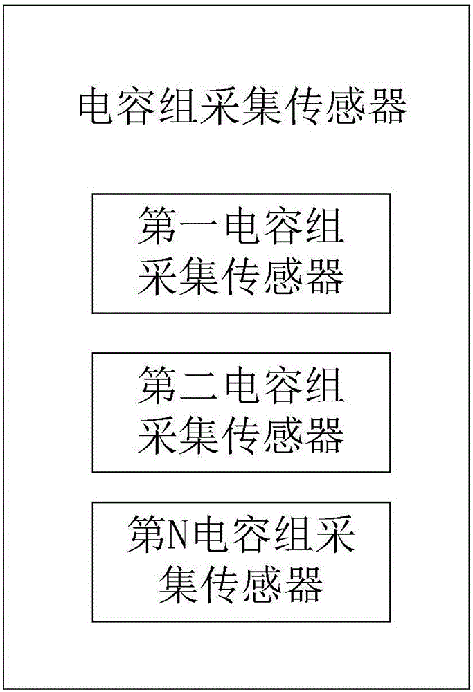
[0042] It also includes a capacitor bank acquisition sensor, which collects the data of each group of capacitors and transmits them to the microcomputer processor, au...


PUM


Abstract

The invention discloses an intelligent combination control system and a redundancy judgment method for an electric power terminal power factor. The intelligent combination control system comprises a microcomputer processor used as the control core, a bus reactive power factor collection sensor as well as a capacitor group collection sensor, wherein the bus reactive power factor collection sensor is used for detecting and calculating the reactive power factor of the bus, and transmitting the reactive power factor to the microcomputer processor; the capacitor group collection sensor is used for collecting the data of each of capacitor group, transmitting the data to the microcomputer processor, automatically recognizing combination and finding the capacitor group with the optimal capacity, and transmitting the capacitor group to a control capacitor group switching apparatus to switch. According to the intelligent combination control system and the redundancy judgment method, the power factor of the electric power terminal is improved while a fully intelligent way is adopted to control; after the capacitor group collection sensor, the temperature sensor and the pressure sensor are detected and judged through the redundancy judgment way, the capacitor group collection sensor, the temperature sensor and the pressure sensor are switched; and the compensation way is combined with a way of increasing the natural power, so that the power factor of the electric power terminal is increased.

Description

technical field [0001] The invention relates to the field of electric power terminal monitoring, in particular to an electric power terminal power factor intelligent combination control system and a redundancy judgment method. Background technique [0002] Power end users refer to factories and enterprises' substations and distribution stations. The level of reactive power factor is directly related to the power loss and energy loss in the power network of power-consuming enterprises, to the voltage loss and voltage fluctuation of the supply voltage, and to the saving of electric energy and the overall The quality of power supply in the power supply area. The power factor indicates the ratio of the active power required by a load to the apparent power; therefore, the normal operation of the power factor is very important. Improving the quality of electricity and improving the operating conditions of the equipment can ensure that the equipment works under normal conditions, w...

Claims


Application Information

Patent Timeline
IPC IPC(8): H02J3/18H02H7/22
CPCY02E40/30H02J3/18H02H7/22
Inventor 吕世全
Owner 吕世全
Learn More