Elevator system comprising destination control system

An elevator system and control system technology, which is applied to elevators, transportation and packaging, elevators and other directions in buildings, can solve problems such as complicated elevator distribution, and achieve the effect of improving efficiency, less experience, and simplifying the layout structure.

Active Publication Date: 2016-08-24
KONE CORP
View PDF2 Cites 6 Cited by
  • Summary
  • Abstract
  • Description
  • Claims
  • Application Information

AI Technical Summary

Problems solved by technology

[0003] Especially in elevator systems used by users unfamiliar with the use of destination control systems, such as on cruise ships, when passengers unfamiliar with the operation of the destination operating panels block a small number of destination operating panels, thereby the destination Problem

Method used


Image

  • Elevator system comprising destination control system
  • Elevator system comprising destination control system
  • Elevator system comprising destination control system

Examples


Embodiment Construction

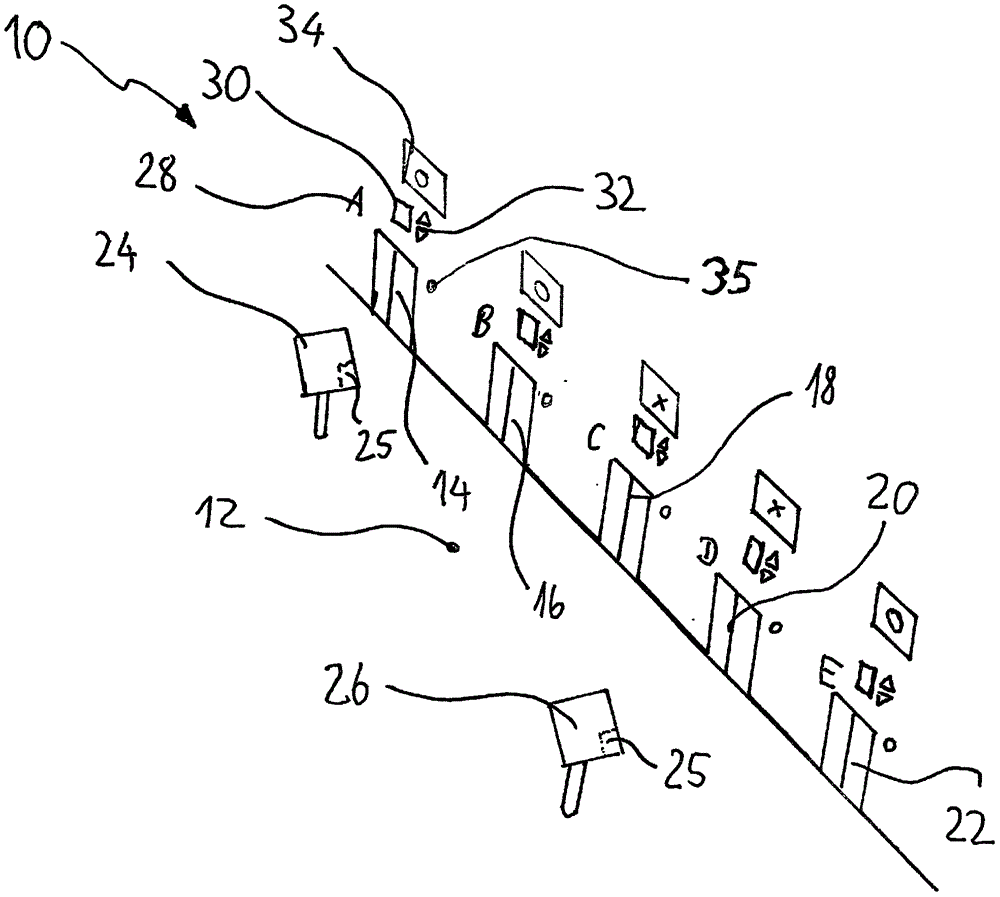
[0039] figure 1 A perspective view of a landing hall 12 of a landing of the elevator system 10 is shown, from which hall there is access to at least five elevators 14 , 16 , 18 , 20 , 22 . In the lobby 12, there are two destination operating panels 24, 26 that include input devices for issuing destination calls, such as ADA keypads, and displays and / or touch screens to indicate to passengers the applicable elevators serving this issued destination , preferably indicated immediately after the destination call has been issued. Each of the five elevators 14-22 has a separate identifier 28, in this example the letters A-E. Each elevator has at its top a hall light arrangement comprising a first display 30 for the actual position of the elevator and a second display 32 for indicating the direction of movement of the elevator.

[0040] Furthermore, each elevator has a range identifier display 34 indicating a certain range of destinations served by that elevator. The range identif...


PUM


Abstract

The invention refers to an elevator system offering sophisticated transport capacity even under conditions where the passengers are not familiar with the use of a destination call system, e.g. on cruise ships. The elevator control system (10) comprises at least one group control with a destination control system (DCS), and at least one elevator group. The at least one elevator group has elevators (14-22) with a different destination range, destination operating panels (DOPs) (24, 26) at each landing, car operating panels (COPs) (38) located in the elevators, hall lantern means (30, 32) indicating the moving direction of their corresponding elevator, and signaling means (32, 35) indicating the arrival of an elevator at the landing (12), wherein the DCS 52 is configured to display, in the vicinty of the elevators a range identifier of the elevators (14-22) serving the destination and to indicate the next arriving elevator.

Description

Background technique [0001] Still the most common in elevator technology is the call distribution method known as continuous call distribution, whereby up / down buttons are provided at each landing and hall light units are arranged on each elevator to give Information about the location and direction of movement of the elevator. The current system uses destination call control, where the passenger enters his destination floor on the destination operator panel, after which the destination control system immediately assigns the best elevator according to a predetermined cost function, which is displayed in the destination on the operation panel. Sometimes the destination operator panel has separate devices for inputting and displaying data, but a combination of input and output devices can also be located on a touchscreen display that is then used to input and display data to passengers. [0002] The present invention particularly relates to a customized destination control sys...

Claims


Application Information

Patent Timeline
IPC IPC(8): B66B1/24B66B3/00B66B9/00
CPCB66B1/2458B66B3/006B66B2201/103B63B29/00B66B1/468B66B2201/301B66B2201/404B66B2201/4623
Inventor J·韦恩霍兹-巴斯S·尼米南J·索萨
Owner KONE CORP
Why Eureka
Try Eureka