
An electric printing head device

A printing head and electric technology, which is applied in the field of electric printing head device and marking device on the steel plate, can solve the problems of immature structure and unsatisfactory effect, achieve the forward punching and returning action simply, improve the durability, and the front Punch and return actions and high-speed effects

Active Publication Date: 2018-08-10
SHANTOU JUNGUO MECHANICAL & ELECTRICAL TECH CO LTD
View PDF4 Cites 0 Cited by
  • Summary
  • Abstract
  • Description
  • Claims
  • Application Information

AI Technical Summary

Problems solved by technology

[0006] In order to overcome the shortcomings of immature structure and unsatisfactory effect in the existing technology applicable to this field, the purpose of the present invention is to provide an improved electric printing head device, which can overcome the defects of the prior art

Method used


Image

  • An electric printing head device
  • An electric printing head device
  • An electric printing head device

Examples


Embodiment Construction

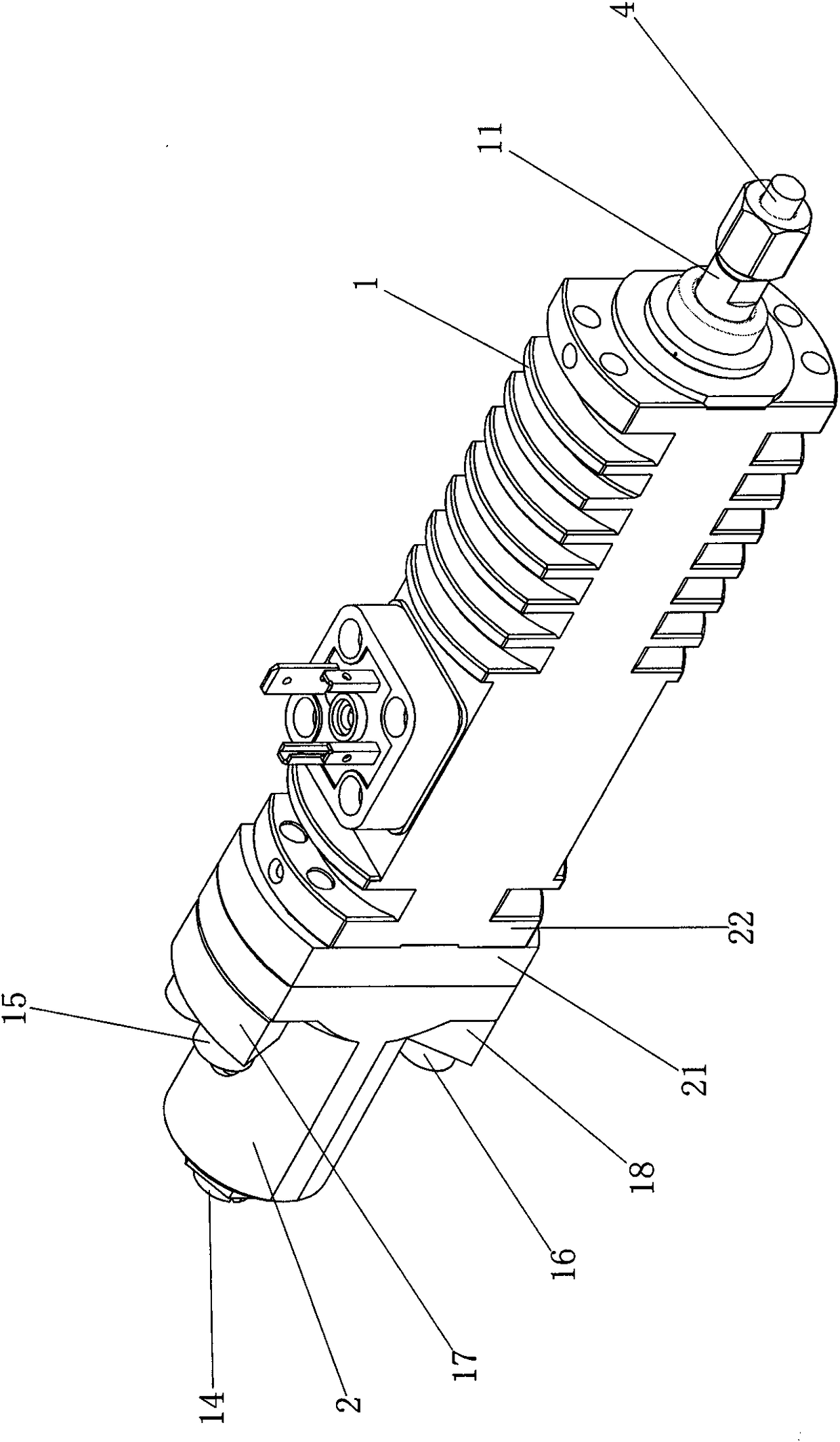
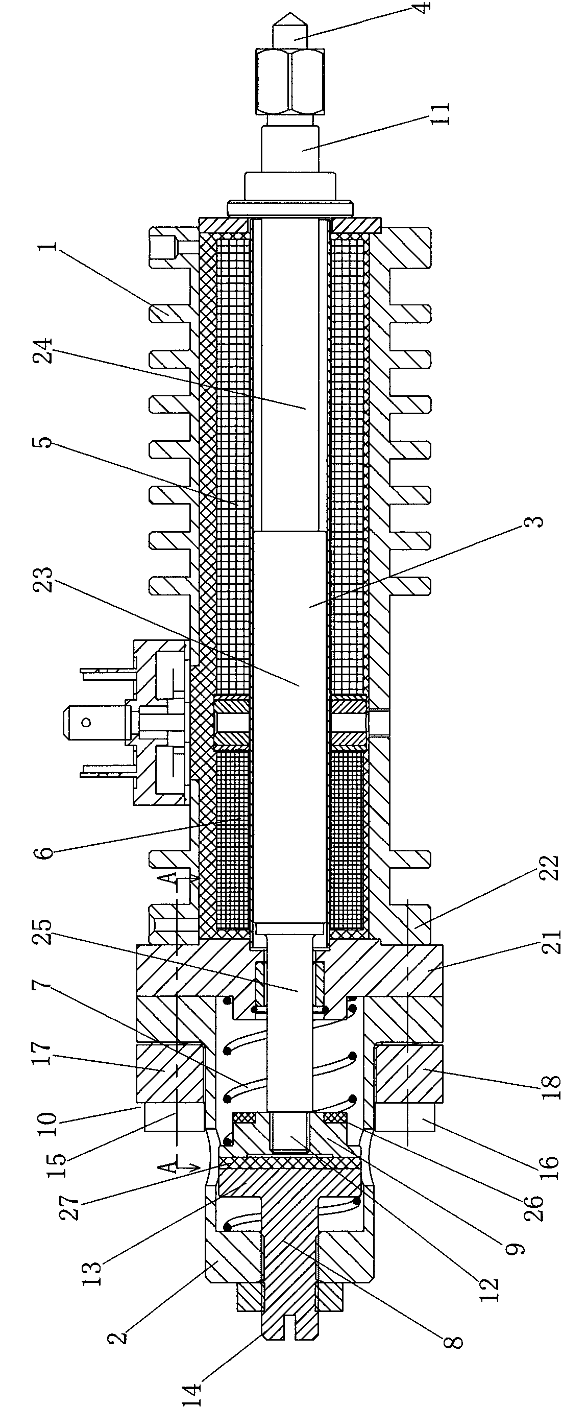
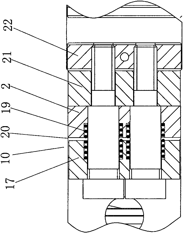
[0020] refer to Figure 1 ~ Figure 3 , the electric print head device is characterized in that it includes a casing 1, a casing back seat 2, a punch rod 3, a punch 4, a forward electromagnetic coil 5, a return electromagnetic coil 6, a return spring 7, and a stroke adjustment stud 8 , the punch tailstock 9 and the return buffer mechanism 10, wherein the punch 4 is slidingly fitted in the housing 1, its front end section 11 exposes the front of the housing 1, and its rear end section 12 exposes the housing 1, the punch 4 is fixed on the front end section 11 of the punch rod 3, the punch tailstock 9 is fixed on the rear end section 12 of the punch rod 3, and the front punch electromagnetic coil 5 is installed on the front part of the cavity of the housing 1 outside the punch 3, the return electromagnetic coil 6 is installed on the rear part of the cavity of the housing 1 outside the punch 3, and the rear seat of the housing 2 The return buffer mechanism 10 is installed on the o...


PUM


Abstract

Provided is an electric marking punch pin device. The electric marking punch pin device aims at overcoming the defects that in the prior art, structures are immature and effects are unsatisfactory. According to the technical scheme, the electric marking punch pin device is characterized by comprising a shell, a shell back base, a punch, a punch pin, a forward punching electromagnetic coil, a return electromagnetic coil, a return spring, a stroke adjusting stud, a punch tailstock and a return buffer mechanism, wherein the punch is arranged on the shell in a sliding fit manner, and the punch pin is fixed to the front end section of the punch, the punch tailstock is fixed to the rear end section of the punch; the forward punching electromagnetic coil is installed on the front portion in the part, on the outer side of the punch, of a shell cavity, the return electromagnetic coil is installed on the rear portion in the part, on the outer side of the punch, of the shell cavity, and the shell back base is installed on the outer side of the rear end of the shell through the return buffer mechanism; the punch tailstock is located in a cavity of the shell back base, the limiting end of the stroke adjusting stud is located behind the punch tailstock arranged in the cavity of the shell back base, and the adjusting end of the stroke adjusting stud is exposed out of the shell back base; and the rear end section of the punch is sleeved with the return spring, one end of the return spring abuts against the punch tailstock, and the other end of the return spring abuts against the outer side of the rear end of the shell.

Description

technical field [0001] The invention relates to a device for making marks on steel materials, especially steel plates, in particular to an electric punching head device. Background technique [0002] During the production of steel plates, steel mills generally put permanent marks on the surface of the steel plates to record the size, weight, material, furnace number, production time, and implementation standards of the steel plates, especially on ship plates, boiler container plates, and export On the steel plate, the above marks must be printed. At present, automatic marking and printing equipment is generally used to mark permanent marks on the surface of steel plates. Chinese patent No. 200920289632.9 discloses a follow-up steel needle printing system, which includes a main beam, a follow-up and synchronous operation mechanism, and a printing head. On the main beam, a number of concave points are punched out on the steel plate by the punching head to form the font. [...

Claims


Application Information

Patent Timeline
Patent Type & Authority Patents(China)
IPC IPC(8): B41K3/40
CPCB41K3/40
Inventor 罗俊生
Owner SHANTOU JUNGUO MECHANICAL & ELECTRICAL TECH CO LTD
Learn More