
Magnet induction steering traction track

A traction track and magnet induction technology, which is applied in the direction of railway vehicle traction devices, tracks, movable tracks, etc., can solve the problems of affecting the transportation efficiency of mine cars, low degree of mechanization, and slow operation process, so as to improve the monitoring and dispatching ability of train operation , reduce safety hazards, and facilitate installation and maintenance

Active Publication Date: 2018-01-02
HUAINAN MINING IND GRP
View PDF8 Cites 0 Cited by
  • Summary
  • Abstract
  • Description
  • Claims
  • Application Information

AI Technical Summary

Problems solved by technology

[0002] The horizontal inclined shaft track of coal mine is generally arranged in two tracks, one is the down line, which is used to transport the empty mine car to the inclined shaft, and the other is the weight car line, which is used to transport the loaded mine car to the horizontal platform marshalling. There are symmetrical turnouts on the two tracks, which can be connected to the above two tracks; according to the arrangement of mine car transportation and marshalling, the horizontal inclined shaft track includes a curved section and a connecting section, which are respectively used for mine car marshalling and transportation ; The existing traction system mainly uses a winch to control the traction of the mine car. The operation process is slow and the degree of mechanization is low. Affected minecart delivery efficiency

Method used


Image

  • Magnet induction steering traction track
  • Magnet induction steering traction track
  • Magnet induction steering traction track

Examples


Embodiment Construction

[0017] The present invention is described in detail below in conjunction with accompanying drawing,

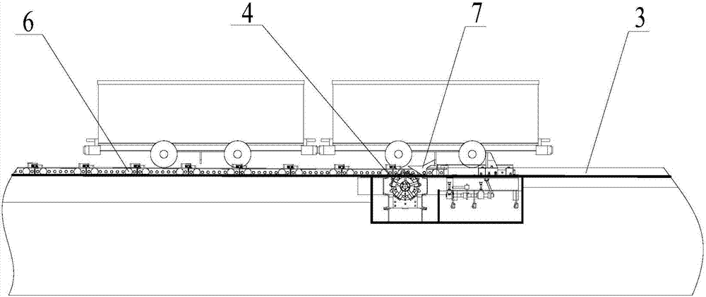
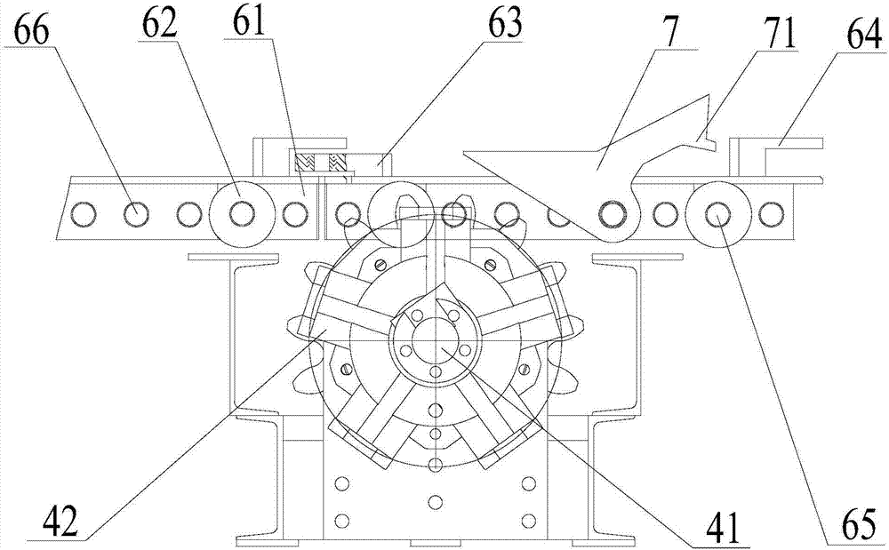
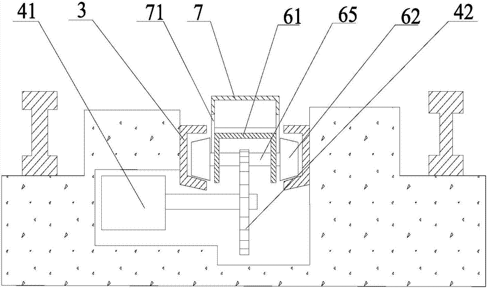
[0018] Such as figure 1 , figure 2 As shown, the magnet induction driving traction track includes a traction track groove 3 and a magnet induction device arranged at the center of the track rail, the traction track groove 3 is provided with a tractor, and the lower part of the traction track groove 3 is provided with a hydraulic transmission device 4. The traction track groove 3 is formed by the relative combination of two rows of U-shaped channel steel notches of the same specification. The tractor is composed of a number of small-wheel vehicles 6 hinged at the front and rear. The articulated shaft rotates horizontally, the upper part of the small wheeled vehicle 6 is provided with a movable push plate 7, the bottom of the small wheeled vehicle 6 is provided with a pin tooth member, and the hydraulic transmission device 4 includes a hydraulic cylinder 41 and a transmission ...


PUM


Abstract

The invention discloses a magnetic induction operation vehicle traction track, comprising a traction track groove and a magnetic induction device. A tractor is arranged on the traction track groove and a hydraulic transmission device is arranged on the lower part of the traction track groove. The traction track groove is formed by oppositely combining two rows of U-shaped steel channel notches at the same specifications, the tractor is formed by connecting multiple small-wheel dollies in a head-tail hinging way front and back, the small-wheel dollies rotate along hinging shafts, a movable push plate is arranged on the upper parts of the small-wheel dollies, a pin gear component is arranged on the bottoms of the small-wheel dollies, the hydraulic transmission device comprises a hydraulic oil cylinder and a transmission output gear, and the transmission output gear is fixedly arranged on the bottoms of the small-wheel dollies, correspondingly meshed with the pin gear component and used for driving the small-wheel dollies to move along the traction track groove; the magnetic induction device comprises multiple induced magnets and multiple magnet detectors, the induced magnets are arranged on the outer walls of the small-wheel dollies through fame supports, and the magnet detectors are arranged on the traction track groove on one side corresponding to the induced magnets.

Description

technical field [0001] The invention relates to the technical field of mine vehicle operation equipment, in particular to a magnet induction vehicle traction track. Background technique [0002] The horizontal inclined shaft track of coal mine is generally arranged in two tracks, one is the down line, which is used to transport the empty mine car to the inclined shaft, and the other is the weight car line, which is used to transport the loaded mine car to the horizontal platform marshalling. There are symmetrical turnouts on the two tracks, which can be connected to the above two tracks; according to the arrangement of mine car transportation and marshalling, the horizontal inclined shaft track includes a curved section and a connecting section, which are respectively used for mine car marshalling and transportation ; The existing traction system mainly uses a winch to control the traction of the mine car. The operation process is slow and the degree of mechanization is low....

Claims


Application Information

Patent Timeline
Patent Type & Authority Patents(China)
IPC IPC(8): B61J3/00E01B23/02
CPCB61J3/00E01B23/02
Inventor 夏仕方蒋幸福李德伟汝岑王健杨更新蔡长利汪志明李跃
Owner HUAINAN MINING IND GRP
Learn More