Sectional warping machine and yarn storing, yarn feeding and leasing system thereof
A technology for storing and feeding yarn on a warping machine, applied in the field of warping, it can solve the problems of tension and winding length error, and it is difficult to ensure the consistency of length, etc., and achieves the effects of high precision, fast data processing speed, and fast start-up.
- Summary
- Abstract
- Description
- Claims
- Application Information
AI Technical Summary
Problems solved by technology
Method used
Image
Examples
Embodiment 1
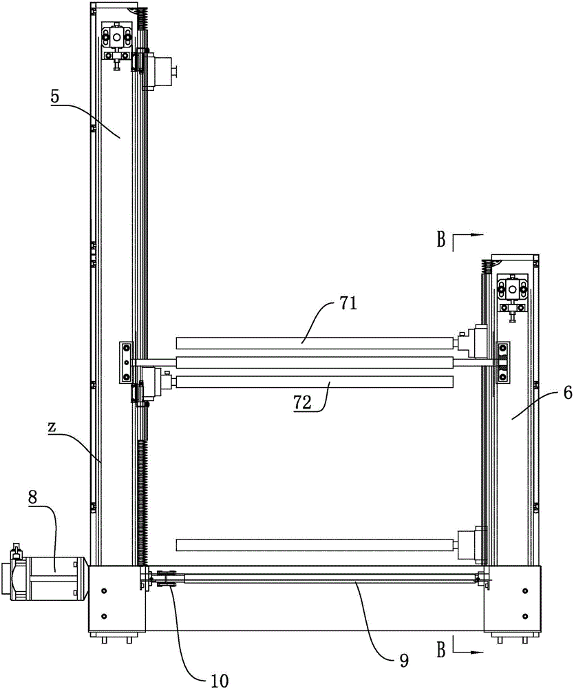
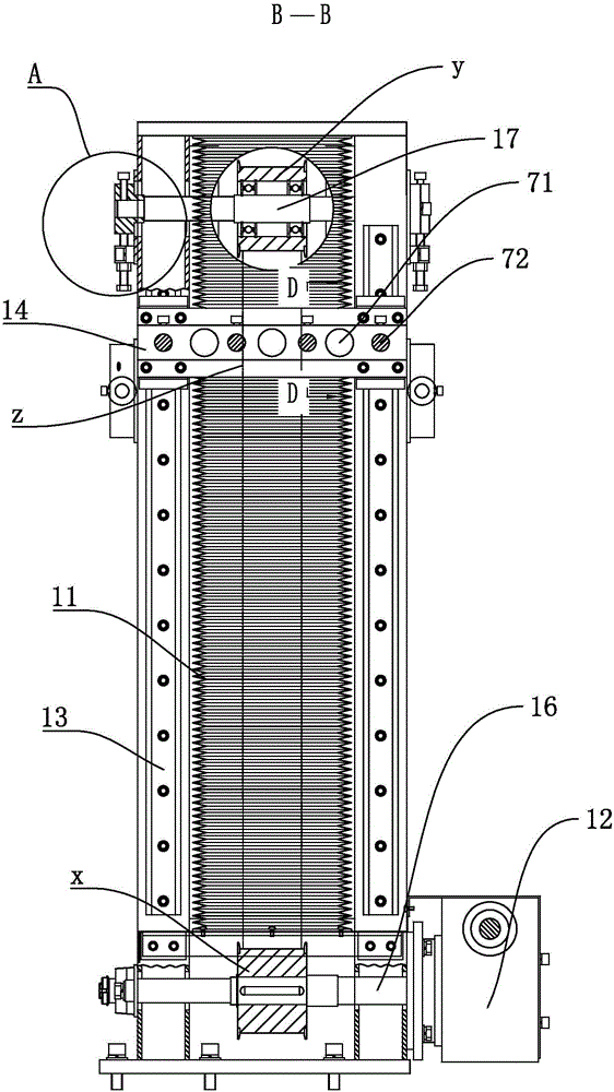
[0047] Embodiment 1: a kind of yarn storage unit of section warping machine, such as figure 1 Shown, comprise vertically arranged long column 5 and short column 6, long column 5 is provided with upper yarn storage roller 71, short column 6 is provided with lower yarn storage roller 72, long column 5 and short column 6 are all provided with There is a linear drive device, and both the upper yarn storage roller 71 and the lower yarn storage roller 72 reciprocate up and down through the linear drive device.
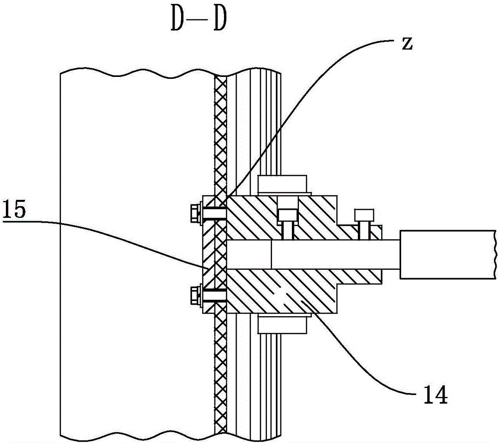
[0048]Both the long column 5 and the short column 6 are provided with a linear drive device, and this embodiment specifically describes the linear drive device on the long column 5 . The linear drive device includes a linear guide rail 13 arranged on the long column 5, slidingly connected to the slider 14 on the linear guide rail 13, and three upper yarn storage rollers 71 are arranged horizontally and linearly on the slider 14 on one side of the long column 5 , the lower y...
Embodiment 2
[0056] Embodiment 2: a kind of section warping machine yarn feeding unit, as Figure 5 As shown, a box body 30 is included, and the box body 30 is provided with a yarn pressing rubber roller 31 and a yarn guide roller 32, and the yarn guide roller 32 is connected to the box body 30 in rotation, and is positioned at the lower side of the yarn pressing rubber roller 31, and the yarn guide roller 32 plays a guiding role, and has a driving device that drives itself to rotate. The driving device is preferably a synchronous motor 34. The output shaft of the synchronous motor 34 is provided with a driving pulley m, and the shaft end of the guide roller 32 is provided with a passive pulley n. A synchronous belt p is sleeved between the driving pulley m and the passive pulley n, and the output rotation of the synchronous motor 34 is linked to the rotation of the yarn guide roller 32, thereby realizing the yarn guide function.
[0057] Such as Figure 6 As shown, the yarn pressing rubb...
Embodiment 3
[0064] Embodiment 3: a kind of warping machine splitting unit 3, such as Figure 8 As shown, it includes a wallboard 50, a linear guide rail 51 located on the wallboard 50, a sub-twisted reed 52 that is slidably connected to the linear guide rail 51, and a driving device that drives the sub-twisted reed 52 to slide. There is a connecting plate, the connecting plate is slidingly connected to the linear guide rail 51, the driving device is preferably a three-position cylinder 531, and the output terminal of the three-position cylinder 531 is connected to the connecting plate, and the split reed 52 is driven in three positions of upper, middle and lower up and down.
[0065] Such as Figure 8 As shown, the skeining unit 3 also includes a yarn clamping device 54 for clamping the yarn to facilitate finding yarn breakage. The yarn clamping device 54 includes two yarn clamping rods located on the side of the skeining reed 52. The yarn clamping rods Located in the stroke of the uppe...
PUM
 Abstract
Description
Claims
Application Information
 - R&D
- Intellectual Property
- Life Sciences
- Materials
- Tech Scout
- Unparalleled Data Quality
- Higher Quality Content
- 60% Fewer Hallucinations
Browse by: Latest US Patents, China's latest patents, Technical Efficacy Thesaurus, Application Domain, Technology Topic, Popular Technical Reports.
© 2025 PatSnap. All rights reserved.Legal|Privacy policy|Modern Slavery Act Transparency Statement|Sitemap|About US| Contact US: help@patsnap.com


