
Plunger pump driving device with automatic compensation function

A driving device and automatic compensation technology, which is applied to the components of pumping devices for elastic fluids, pumps with flexible working elements, pumps, etc., can solve the problems of difficult assembly and adjustment of negative pressure parameters, complex structure, etc. Reduce the difficulty of processing and assembly adjustment, achieve intermittent lubrication, and simplify the structure

Active Publication Date: 2016-08-31
SHAANXI UNIV OF TECH
View PDF5 Cites 5 Cited by
  • Summary
  • Abstract
  • Description
  • Claims
  • Application Information

AI Technical Summary

Problems solved by technology

[0003] The purpose of the present invention is to provide an automatic compensating plunger pump driving device, which solves the problems of complex structure, difficult assembly and negative pressure parameter adjustment of the oil supplement valve of the existing hydraulic diaphragm pump

Method used


Image

  • Plunger pump driving device with automatic compensation function
  • Plunger pump driving device with automatic compensation function
  • Plunger pump driving device with automatic compensation function

Examples


Embodiment Construction

[0030] The present invention will be described in detail below in conjunction with the accompanying drawings and specific embodiments.

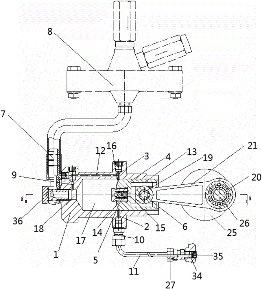
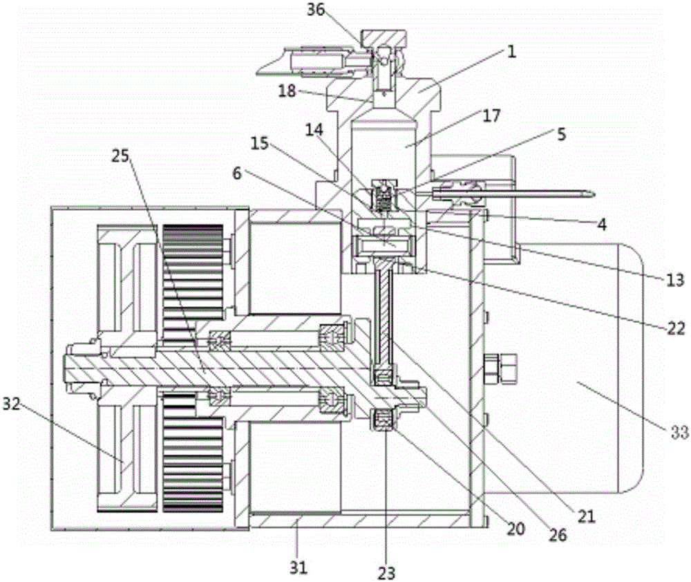
[0031] The present invention is an automatic compensating plunger pump driving device, the structure is as follows: figure 1 , 2 As shown, it includes a hollow cylinder body 1, a plunger 4 is arranged inside the cylinder body 1, a constant pressure relief valve 5 is arranged inside the plunger 4, a plunger pin 6 is arranged on the plunger 4, and a plunger pin 6 is arranged on the plunger pin 6 Connect the crank drive mechanism, the cylinder 1 is connected with the hydraulic cavity of the quantitative diaphragm pump head 8 (the quantitative diaphragm pump head 8 can be any existing hydraulic quantitative diaphragm pump head) through the right angle-articulated rubber hose assembly 7, The cylinder body 1 is connected to the oil storage tank through a hose 11 .

[0032] The side wall of the cylinder body 1 is respectively provided with a stepp...


PUM


Abstract

The invention discloses a plunger pump driving device with an automatic compensation function. The plunger pump driving device with the automatic compensation function comprises a hollow cylinder, wherein a plunger is arranged inside the cylinder; a constant pressure overflow valve is arranged inside the plunger; a plunger pin is arranged on the plunger and connected with a crank driving mechanism; the cylinder is connected with a hydraulic cavity of a constant delivery diaphragm pump head; and the cylinder is connected with an oil storage tank through a hose. According to the plunger pump driving device with the automatic compensation function, the problems that an oil supplementary valve of an existing hydraulic diaphragm pump is complicated in structure, and assembling and negative pressure parameter adjustment are difficult are solved.

Description

technical field [0001] The invention belongs to the technical field of hydraulic diaphragm pumps, and relates to an automatic compensation plunger pump driving device. Background technique [0002] The hydraulic diaphragm pump relies on the reciprocating movement of the plunger to make the hydraulic fluid in the closed working chamber move forward and retreat, and the diaphragm is driven to perform a protruding-backward deformation movement, and the pressure in the working chamber forms a periodic change of high pressure-negative pressure with the reciprocating movement of the plunger. When the working chamber is under high pressure, it is overflowed by the overflow valve, and when it is under negative pressure, it is replenished by the oil supply valve. The traditional oil supply valve has complex structure, high machining accuracy, and difficult assembly and adjustment of negative pressure parameters. Contents of the invention [0003] The object of the present invention...

Claims


Application Information

Patent Timeline
Patent Type & Authority Applications(China)
IPC IPC(8): F04B43/067F04B53/12F04B53/18F04B53/14F04B53/16
CPCF04B43/067F04B53/12F04B53/14F04B53/162F04B53/18
Inventor 杨永平孟欣
Owner SHAANXI UNIV OF TECH
Learn More