Harvester gearbox output shaft mechanism and harvester gearbox

A technology for gearboxes and harvesters, applied in the field of gearboxes, can solve the problems of reducing product performance, cumbersome processes, affecting the structural accuracy and service life of gearboxes, etc., to improve service life and stability, simple and compact structure, and easy maintenance. effect used

Active Publication Date: 2016-08-31
CHUZHOU YUEDA IND
View PDF7 Cites 2 Cited by
  • Summary
  • Abstract
  • Description
  • Claims
  • Application Information

AI Technical Summary

Problems solved by technology

In the existing harvester gearbox structure, the bottom ends of the left and right half shafts are provided with hoops, and the hoops are abutted on the transmission output gear, so that a limit is formed between the half shaft and the transmission output gear. The structural setting makes the installation and maintenance of the gearbox output shaft very inconvenient: when the half shaft needs to be taken out for replacement or maintenance, the gearbox needs to be disassembled as a whole, and then the casing is opened, the clamp is removed, and the limit is released before the half shaft can be taken out , the installation process also needs to repeat the above process, and the process is cumbersome; and the multiple overall disassembly and installation also greatly affects the structural accuracy and service life of the gearbox, reducing product performance

Method used


Image

  • Harvester gearbox output shaft mechanism and harvester gearbox
  • Harvester gearbox output shaft mechanism and harvester gearbox
  • Harvester gearbox output shaft mechanism and harvester gearbox

Examples


Embodiment Construction

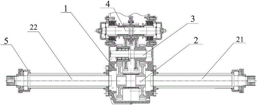
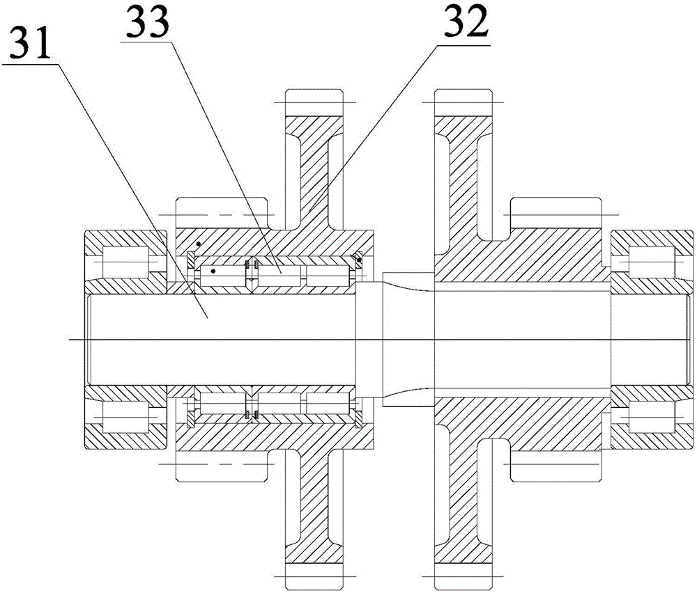
[0019] Such as picture 1 , picture 2 As shown, a harvester gearbox includes a gearbox housing 1 and an output shaft mechanism 2, an idler shaft part 3, and a steering clutch shaft part 4 arranged in the housing 1;

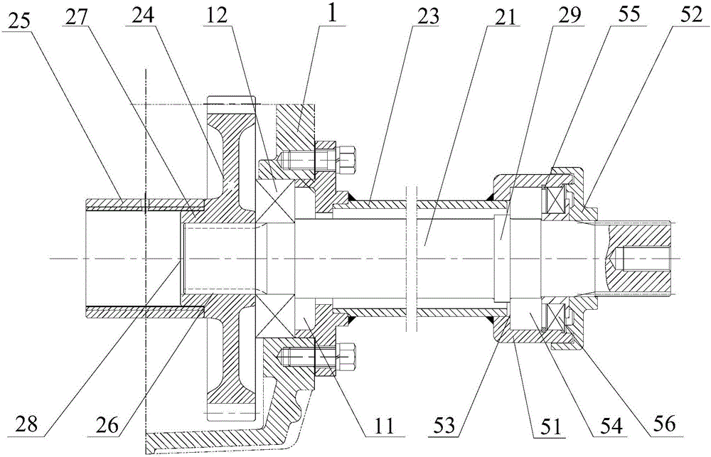
[0020] The output shaft mechanism 2 includes a left half shaft 21, a right half shaft 22 and a corresponding half shaft sleeve 23, and the left 21 and right half shaft 22 are rotatably and fixedly sleeved in the half shaft sleeve 23. The output shaft mechanism 2 also includes a transmission output gear 24 and a process retaining ring 25. The center of the transmission output gear 24 is provided with a mounting hole 26 with an internal spline. The left 21, right half shaft The outer edge of the bottom of 22 is provided with corresponding external splines. The bottoms of the left 21 and right half shafts 22 pass through the mounting holes 26 and are spline-coupled with the transmission output gear 24. The outer edges of the transmission output gear 24 are inst...


PUM


Abstract

The invention discloses a harvester gearbox output shaft mechanism and a harvester gearbox. The output shaft mechanism comprises a left half shaft, a right half shaft and half shaft sleeves. The left half shaft and the right half shaft are rotationally fixed and installed in the half shaft sleeves in a sleeved mode, and the two ends of the left half shaft and the two ends of the right half shaft extend outwards. The output shaft mechanism further comprises transmission output gears and a process retainer ring. The centers of the transmission output gears are provided with installation holes with inner splines, and corresponding outer splines are arranged at the outer edge of the bottom of the left half shaft and the outer edge of the bottom of the right half shaft. The bottom of the left half shaft and the bottom of the right half shaft penetrate through the installation holes and are connected with the transmission output gear splines. Annular protrusions are arranged at the outer edges of the transmission output gear installation holes. The bottom end surface of the left half shaft and the bottom end surface of the right half shaft are flush with the end surfaces of the annular protrusions. The process retainer ring is arranged between the transmission output gears at the bottom end of the left half shaft and the bottom end of the right half shaft, and the two ends of the process retainer ring are connected to the centers of the side walls of the transmission output gears in an abutting mode. Grooves corresponding to the annular protrusions are formed in the two ends of the process retainer ring. The concave surfaces of the grooves are in butt joint with the annular protrusions, the bottom end surface of the left half shaft and the bottom end surface of the right half shaft.

Description

technical field [0001] The invention relates to the technical field of gearboxes, in particular to an output shaft mechanism of a harvester gearbox and a harvester gearbox. Background technique [0002] The gearbox is one of the key components of the harvester, which is used to control the movement of the harvester, such as forward and backward, left and right steering, acceleration and deceleration, etc. The gearbox of the harvester mainly includes a housing, an output shaft mechanism, a steering clutch mechanism, and an idler shaft mechanism etc., wherein the output shaft mechanism mainly includes a left half shaft, a right half shaft and corresponding half shaft sleeves, the left and right half shafts are rotatably and fixedly sleeved in the half shaft sleeves, and their bottom ends extend into the gear shifting The box housing is clamped with the transmission output gear in the housing, and its top is the output end, which is used to connect the running parts such as tir...

Claims


Application Information

Patent Timeline
Patent Type & Authority Applications(China)
IPC IPC(8): F16H57/023F16H57/021A01D69/06
CPCA01D69/06F16H57/021F16H57/023F16H2057/02056F16H2057/0235
Inventor 黄泽伟
Owner CHUZHOU YUEDA IND
Why Eureka
Try Eureka