Fixed loading shell decomposer

A decomposing machine and artillery shell technology, applied in the directions of ammunition, weapon accessories, offensive equipment, etc., can solve the problems of low processing efficiency of artillery shell decomposing technology, and achieve the effect of simple structure and high efficiency

Active Publication Date: 2016-08-31
ARMY ENG UNIV OF PLA
View PDF5 Cites 12 Cited by
  • Summary
  • Abstract
  • Description
  • Claims
  • Application Information

AI Technical Summary

Problems solved by technology

[0002] The processing efficiency of the traditional shell decomposition technology is low, therefore, a new shell combination technology is needed to replace the existing technology

Method used


Image

  • Fixed loading shell decomposer
  • Fixed loading shell decomposer

Examples


Embodiment Construction

[0015] Preferred embodiments of the present invention are described below, and those skilled in the art will be able to implement them using related technologies in the field as described below, and can better understand the innovations and benefits of the present invention.

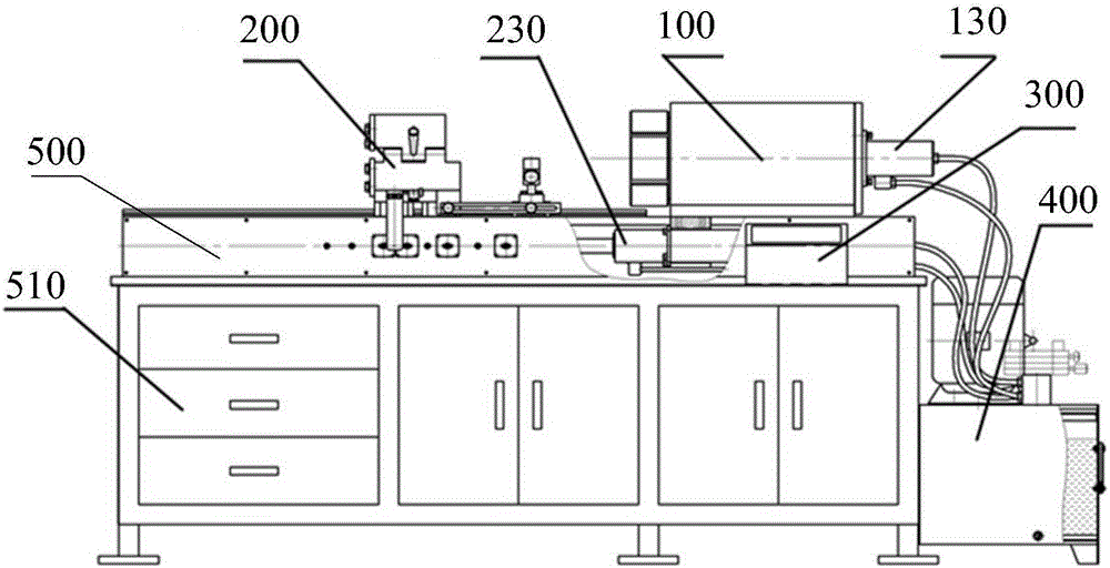
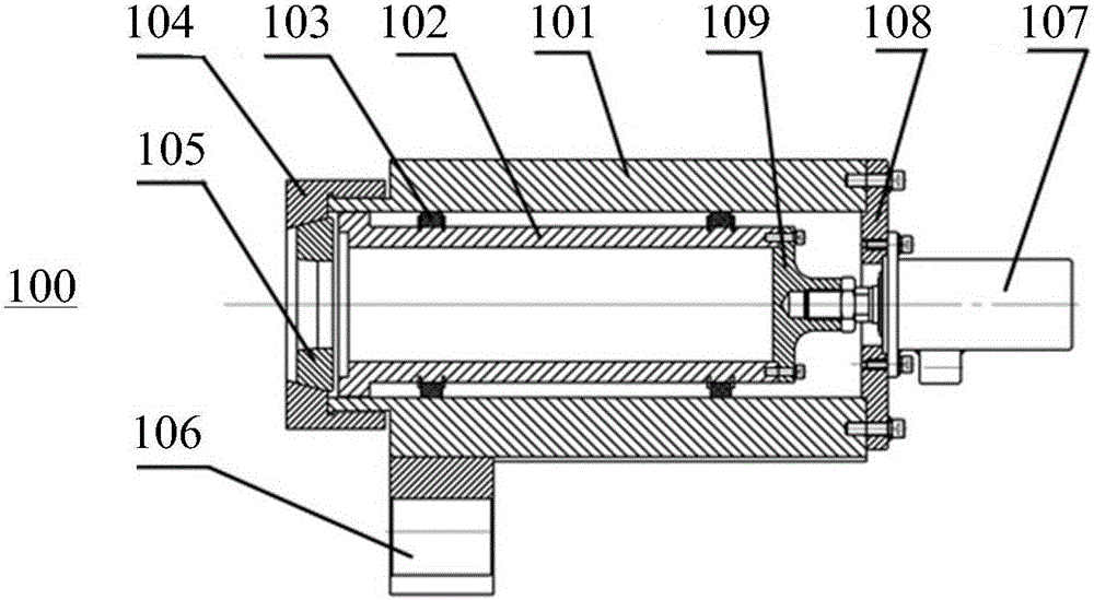
[0016] Such as Figure 1-2 Shown is a fixed-mounted shell disintegrator described in this embodiment, a fixed-mounted shell disassembler, comprising: a bracket 500, a fixed nose 100 and a sliding tail 200; the fixed nose 100 is set On the bracket 500, the fixed machine head 100 includes a shaft sleeve 102 arranged in the machine head housing 101, and a pulley sleeve 103 is arranged between the shaft sleeve 102 and the machine head housing 101 so that the shaft sleeve 102 can Move axially in the machine head housing 101, the front end of the shaft sleeve 102 is provided with a clamping elastic mold 105, and the clamping elastic mold 105 is sleeved on the said machine head housing 101 through a fixed sleev...


PUM


Abstract

The invention discloses a fixed loading shell decomposer comprising a support, a fixed machine head and a slip machine tail; the fixed machine head is arranged on the support, and comprises a shaft sleeve arranged in the machine head housing; a pulley sleeve is arranged between the shaft sleeve and the machine head housing so as to enable the shaft sleeve to axially move in the machine head housing; the front end of the shaft sleeve is provided with a shell clamp die; the shell clamp die is sleeved on the machine head housing through a fixed sleeve; the tail of the machine head housing is provided with a decompose drive unit used for driving the shaft sleeve to axially move, thus compacting the shell clamp die to make radial contraction; the slip machine tail is arranged on the support through a guide rail, and provided with a machine tail drive mechanism used for driving the slip machine tail; the slip machine tail comprises a clamp mechanism used for clamping a gun barrel tail; the whole process enforcement structure is simple, and efficiency is high.

Description

technical field [0001] The invention relates to the technical field of military industry, and more specifically, relates to a fixed-mount shell disintegrating machine. Background technique [0002] The processing efficiency of the traditional shell decomposition technology is low, therefore, a new shell combination technology is needed to replace the existing technology. Contents of the invention [0003] The technical problem to be solved by the present invention is to provide a fixed-installed cannonball disintegrator with high efficiency and good precision. [0004] The purpose of the present invention is achieved through the following technical solutions: a fixed-mounted shell decomposition machine, comprising: a bracket, a fixed head and a sliding tail; the fixed head is arranged on the support, and the fixed head It includes a shaft sleeve arranged in the machine head housing, a pulley sleeve is arranged between the shaft sleeve and the machine head housing so that ...

Claims


Application Information

Patent Timeline
Patent Type & Authority Applications(China)
IPC IPC(8): F42B33/06
CPCF42B33/06
Inventor 张怀智谢俊磊曹宏安黄鹏波李银川
Owner ARMY ENG UNIV OF PLA
Why Eureka
Try Eureka