
Active power measurement circuit

A technology for active power and measuring circuits, which is applied in the direction of measuring electric power, measuring electric variables, and electric power measurement through current/voltage, etc. Reasonable and orderly hardware connection, low hardware requirements, and strong anti-interference ability

Active Publication Date: 2019-04-16
彭志辉
View PDF13 Cites 1 Cited by
  • Summary
  • Abstract
  • Description
  • Claims
  • Application Information

AI Technical Summary

Problems solved by technology

This circuit can be applied to the active power measurement of any AC waveform signal, but there is either an analog multiplier and an integrating circuit to realize or high-precision AD sampling to realize, and the anti-interference ability is poor, thereby reducing the accuracy; Fourier transform and the Hilbert filter method can get better measurement results, but the Fourier transform method has a large amount of calculation and has the problems of spectrum leakage and frequency resolution limitation. The signal to be analyzed must be steady state, and the Hilbert filter design is relatively difficult Difficult. At the same time, the Fourier transform and Hilbert filter methods have very high requirements on hardware performance. Generally, high-performance digital signal processors are required to implement, and the cost is relatively high.

Method used


Image

  • Active power measurement circuit
  • Active power measurement circuit
  • Active power measurement circuit

Examples


Embodiment Construction

[0026] The present invention will be further described below in conjunction with the accompanying drawings and embodiments, but not as a basis for limiting the present invention.

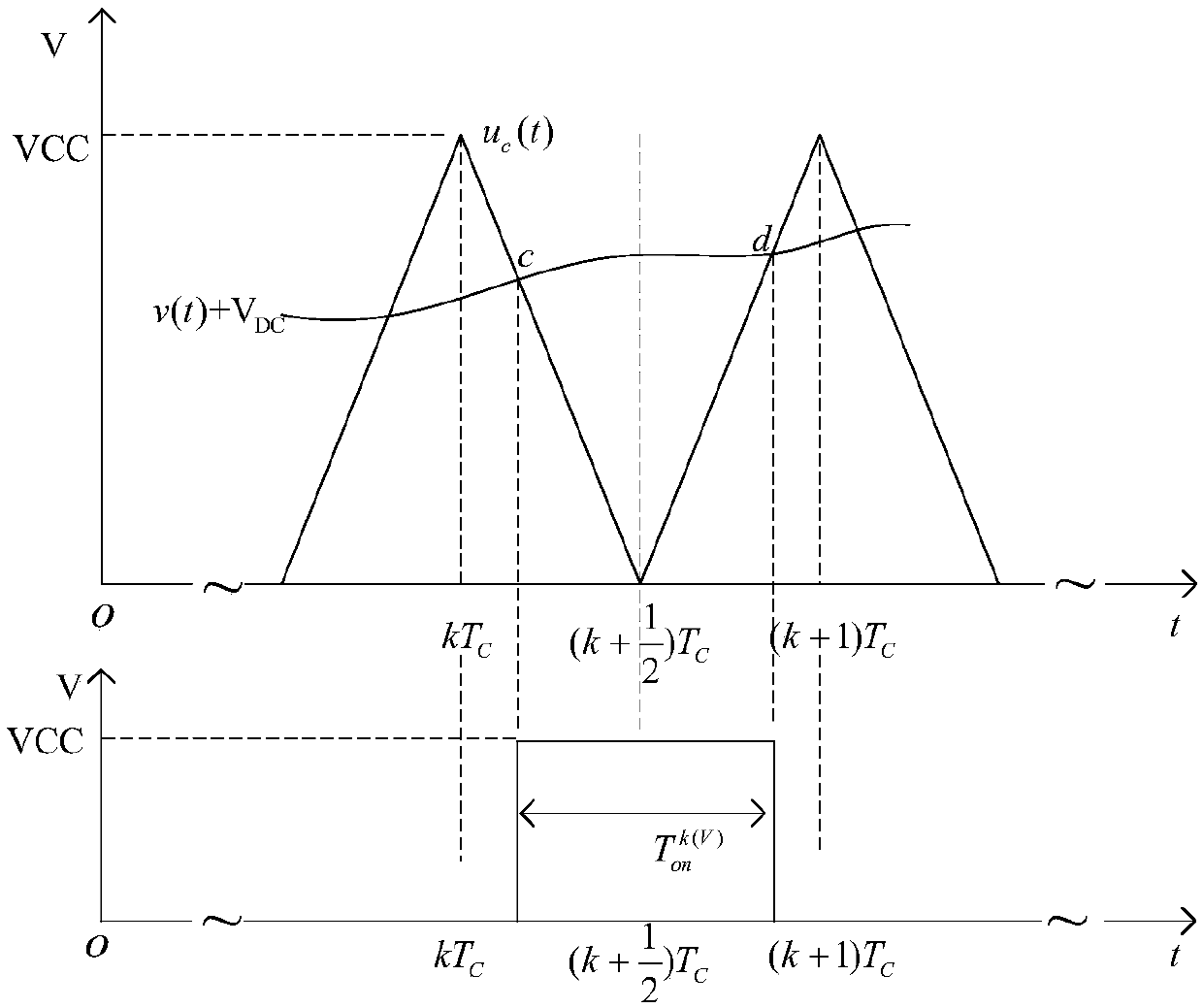
[0027] Example. Suppose the AC voltage signal v(t) to be tested, the DC bias voltage V DC : 0DC DC Satisfy: VCC>(v(t)+V DC )>0. u c (t) is a non-negative symmetrical triangular wave signal, which satisfies: Among them: the period is T C , the frequency is f C , the amplitude is VCC. v(t)+V DC with u c (t) relation as figure 2 Shown:

[0028] because:

[0029]

[0030] and:

[0031]

[0032]

[0033] so:

[0034]

[0035] also because:

[0036]

[0037] F:

[0038]

[0039] in:

[0040] because:

[0041]

[0042] so:

[0043]

[0044] When T C Very small, there are:

[0045]

[0046] Similarly, when VCC>(i(t)+V DC )>0, i(t)+V DC with u c When the relationship of (t) is consistent with the above, there are:

[0047]

[0048] In the AC power sup...


PUM


Abstract

The invention discloses an active power measurement circuit. The circuit comprises a first signal conditioning circuit, a first addition circuit, a current-voltage conversion circuit, a second signalconditioning circuit, a second addition circuit, a shaping circuit, an F / V conversion circuit, an amplifying circuit, a triangular wave generating circuit, a first PWM modulation circuit, a second PWMmodulation circuit, a first timer, a second timer, a first right shift register, a second right shift register, and an active power calculation circuit. In the invention, stability and accuracy can be increased and cost is low.

Description

technical field [0001] The invention relates to an active power measurement circuit, in particular to an active power measurement circuit based on a mathematical model of conduction time, signal frequency, bias voltage and active power. Background technique [0002] Active power is one of the important power parameters of the power system. Active power measurement is not only a necessary link to understand the user's electricity consumption status and accumulated electric energy, but also the only means for the power sector to achieve energy regulation and market operation. Fast and accurate measurement of active power has always been an important research topic in the field of power measurement. [0003] At present, the commonly used active power measurement methods mainly include power triangulation method, analog multiplier method, Fourier transform method, Hilbert filter method, wavelet transform method and so on. However, these measurement methods all have certain lim...

Claims


Application Information

Patent Timeline
Patent Type & Authority Applications(China)
IPC IPC(8): G01R21/00G01R21/06
CPCG01R21/002G01R21/06
Inventor 彭志辉
Owner 彭志辉
Learn More