Seismostation test device for power transmission tower line system

A test device and seismic station technology, which is applied in the direction of measuring device, machine/structural component test, vibration test, etc., can solve the problem of not being able to truly reflect the dynamic characteristics and seismic response of high-voltage transmission lines, and ignore the transmission tower and conductor in the detection of seismic performance. Ground wires interact with each other, can not truly reflect the power transmission system or the stress state of a single tower, etc., to achieve good vibration excitation effect, good corrosion resistance effect, and improve the effect of application range

Active Publication Date: 2016-08-31
CHINA ELECTRIC POWER RES INST +3
View PDF4 Cites 1 Cited by
  • Summary
  • Abstract
  • Description
  • Claims
  • Application Information

AI Technical Summary

Problems solved by technology

[0003] The vibration detection device of the existing transmission tower only tests the anti-seismic performance of one transmission tower, ignoring the mutual influence between the transmission tower and the transmission tower, and between the transmission tower and the ground wire
The following problems will be involved: ①The boundary conditions of the transmission tower are ignored, and the real force state of the transmission system or single tower cannot be truly reflected, which affects the detection data
②Transmission towers are tower-line-tower-line-tower and so on. The transmission tower test should not only have a single tower, but also consider the wires on both sides of the tower and adjacent towers, which cannot truly reflect the high-voltage transmission lines and towers. Dynamic characteristics and seismic response of solid structures under earthquake action
③The cost of transportation and testing is high and the construction schedule is difficult to control
④ Not suitable for areas with steep mountain roads, lack of construction materials, and large-scale construction machinery handling and work

Method used


Image

  • Seismostation test device for power transmission tower line system
  • Seismostation test device for power transmission tower line system
  • Seismostation test device for power transmission tower line system

Examples


Embodiment Construction

[0050] The specific implementation manners of the present invention will be further described in detail below in conjunction with the accompanying drawings.

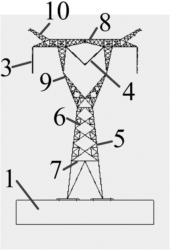
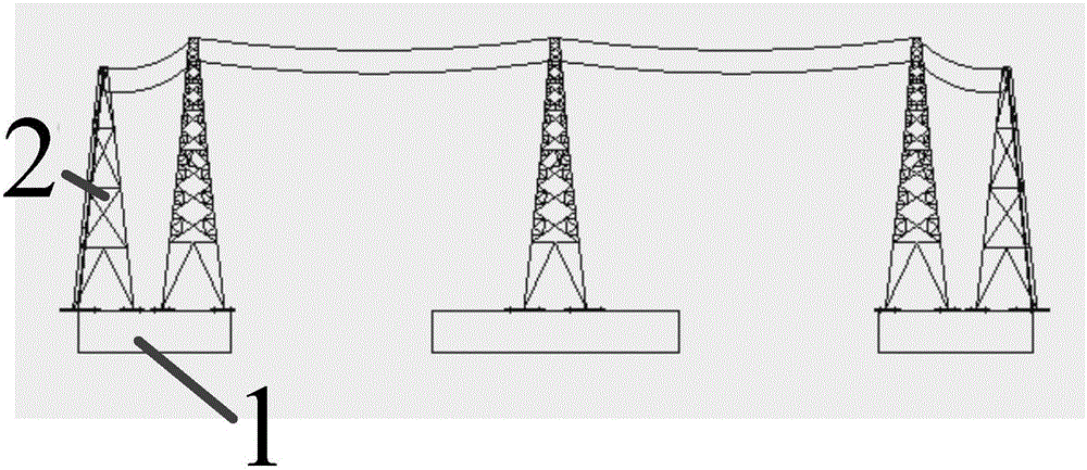
[0051] Such as figure 2 As shown, an embodiment of the present invention provides a seismic table test device for a transmission tower line system, the transmission tower line system includes a vertically arranged tower body, and a tower head arranged laterally on the upper end of the tower body. The model tower, the seismic table test device includes an equivalent tower 2 arranged in parallel with the model tower and a fixed foundation 1 arranged at the lower end of the equivalent tower 2,

[0052] There are three or more model towers, and each model tower is connected by two layers of steel strands respectively arranged on its top;

[0053] The steel strands arranged on the upper floor pass through the equivalent generation tower 2 and are connected to the fixed foundation 1,

[0054] The steel stranded wire arrange...


PUM


Abstract

The invention relates to a seismostation test device for a power transmission tower line system, and the power transmission tower line system comprises a vertical tower body and model towers disposed at the upper end of the tower body in a lateral direction and composed of a tower head. The device comprises an equivalent tower parallel to the model towers, and a fixed base disposed at the lower end of the equivalent tower. The number of the model towers is three or more, and each model tower is connected through two steel strand layers disposed at the top. The upper steel strand passes through the equivalent tower to be fixedly connected with the fixed base, and the lower steel strand is a strand connected with an I-shaped insulating string or a V-shaped insulating string, and two ends of the lower steel strand are respectively connected with the equivalent tower. Compared with the prior art, the device provided by the invention gives full consideration to the boundary condition, so as to truly reflect the stress state of a tower line system or a single tower, to improve the application range, and reduce the cost.

Description

technical field [0001] The invention relates to a seismic table test device, in particular to a seismic table test device for a power transmission tower line system. Background technique [0002] The transmission tower is the pillar of power transmission, and its safety and reliability directly affect the safety and operation of the entire power system. When an earthquake occurs, the transmission tower will be damaged or even collapsed, which will affect social life, bring economic losses, and then affect the development of the national economy. Therefore, a seismic table test device for the transmission tower line system is needed to detect the seismic performance of the transmission tower during geological disasters such as earthquakes. [0003] The vibration detection device of the existing transmission tower only detects the anti-seismic performance of one transmission tower, ignoring the mutual influence between the transmission tower and the transmission tower, and be...

Claims


Application Information

Patent Timeline
Patent Type & Authority Applications(China)
IPC IPC(8): G01M7/02
CPCG01M7/02
Inventor 王飞杨风利黄福云熊铮晖田晓刘亚多汪长智刘海锋韩军科张子富
Owner CHINA ELECTRIC POWER RES INST
Why Eureka
Try Eureka