

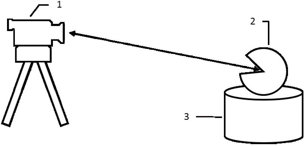
Large-view-field camera calibration method based on laser tracker
A laser tracker and camera calibration technology, applied in the field of visual measurement, can solve the problems of inability to solve errors, a large number, and the acquisition of pre-calibration control points is time-consuming, and achieves the effect of improving accuracy and calibration accuracy.
- Summary
- Abstract
- Description
- Claims
- Application Information
AI Technical Summary
Problems solved by technology
Method used
Image

Examples
Embodiment Construction
[0023] A method for calibrating a camera with a large field of view based on a laser tracker proposed by the present invention will be further described in detail below in conjunction with the accompanying drawings and specific embodiments.
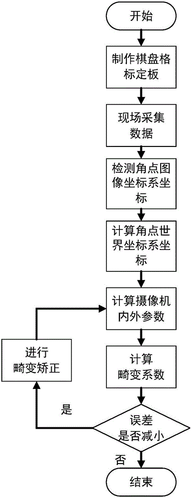
[0024] A calibration method for a large field of view camera based on a laser tracker proposed by the present invention, the process of which is as follows figure 2 shown, including the following steps:
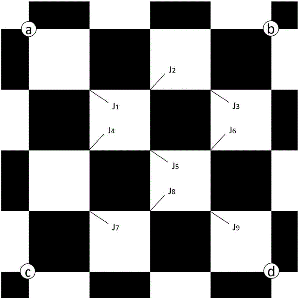
[0025] 1) Make a checkerboard calibration board whose cells are square; make a black and white checkerboard calibration board (the higher the accuracy of the calibration board, the better, and the accuracy is 1 mm in this embodiment), set the number of corner points of the checkerboard as Length × Height, Length represents the number of columns of the calibration board, Height represents the number of rows of the calibration board, (the number of rows and columns of the calibration board can be different), the cells of the calibration b...
PUM
 Abstract
Description
Claims
Application Information