Automobile solenoid valve coil winding process

A technology of solenoid valve coil and winding process, which is applied in coil manufacturing, inductor/transformer/magnet manufacturing, circuit, etc., and can solve problems such as welding broken coil, low cost, and large winding side angle

Active Publication Date: 2016-08-31
苏州创易技研股份有限公司
View PDF5 Cites 1 Cited by
  • Summary
  • Abstract
  • Description
  • Claims
  • Application Information

AI Technical Summary

Problems solved by technology

[0002] The traditional coil winding is wound by hand or semi-automatic machinery. The copper wire is wound by hand, and then the wire is wound mechanically. Finally, the copper wire at the other end is pulled off by hand and wound to another pin. The operation method is inefficient, the effect is poor, and the labor cost is high
There are some winding machines on the market, which first wrap a pin from the inside to the outside, then wind the coil from the outermost lead of the pin, and finally wind the other pin from the inside to the outside. However, since the first pin is bound from the inside to the outside, it is easy to break the copper wire on the outermost circle of the pin when the pin is spot-welded, causing the coil to be easily damaged and the yield rate to be low.
At the same time, when fully automatic winding and hanging, the wire can only be hung from low to high, and then hang down to the bottom of the skeleton. The defect rate is rising, and the general coil winding speed is only 600-800 per hour, and the winding speed needs to be improved
Therefore, in view of the shortcomings of the above-mentioned technical problems in the operation mode of traditional coil winding and the cu...

Method used


Image

  • Automobile solenoid valve coil winding process
  • Automobile solenoid valve coil winding process

Examples


Embodiment Construction

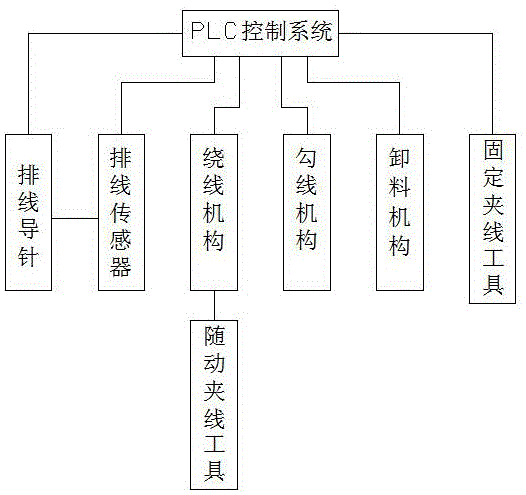
[0017] In this example, refer to Figure 1 to Figure 2 As shown, a kind of automobile electromagnetic valve coil winding process of the present invention, comprises PLC control system, and the cable guide needle that is connected with PLC control system respectively, cable sensor, winding mechanism, hooking mechanism, unloading mechanism and A fixed thread clamping tool, and a follow-up thread clamping tool connected with the winding mechanism, and the thread arranging guide pin is connected with the cable arranging sensor. The object of the automobile solenoid valve coil winding is the solenoid valve coil skeleton. The solenoid valve coil skeleton is composed of a coil and two pins. The two pins include the left pin and the right pin. The left pin and the right pin are respectively located on Both ends of the bobbin.

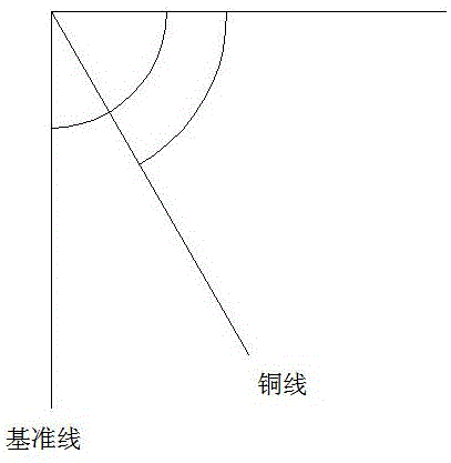
[0018] In one embodiment, the coil winding process steps of the automobile solenoid valve are as follows: step 1, the fixed clamping tool moves forward and cl...


PUM


Abstract

The invention provides an automobile solenoid valve coil winding process. According to the process, a PLC control system and a winding displacement guide pin, a winding displacement sensor, a winding mechanism, a wire hooking mechanism, a striping mechanism and a fixed wire clamping tool which are connected with the PLC control system and a follow-up wire clamping tool connected with the winding mechanism are included. The winding displacement guide pin, the winding displacement sensor, the winding mechanism, the wire hooking mechanism, the fixed wire clamping tool and the striping mechanism are arranged and in control connection with the PLC control system, and the follow-up wire clamping tool and the striping mechanism achieve winding of an automobile solenoid valve coil; the winding mechanism drives a solenoid valve coil framework to conduct winding, the winding displacement guide pin swings leftwards and rightwards to conduct winding displacement, the winding displacement sensor is actually fed back to the PLC control system according to the swing angle alpha of the winding displacement guide pin, and the PLC control system calculates out the winding displacement speed according to the winding displacement calculation formula, so that winding displacement is conducted by dynamically controlling the winding displacement speed of the winding displacement guide pin; the wire hooking mechanism guides a copper wire and conducts pin winding on a left pin from low to high, and fully automatic winding is achieved.

Description

technical field [0001] The invention relates to a coil winding process of an automobile electromagnetic valve. Background technique [0002] The traditional coil winding is wound by hand or semi-automatic machinery. The copper wire is wound by hand, and then the wire is wound mechanically. Finally, the copper wire at the other end is pulled off by hand and wound to another pin. The operation mode has low efficiency, poor effect and high labor cost. There are some winding machines on the market, which first wrap a pin from the inside to the outside, then wind the coil from the outermost lead of the pin, and finally wind the other pin from the inside to the outside. However, since the first pin is bound from the inside to the outside, it is easy to break the copper wire on the outermost circle of the pin during spot welding, causing the coil to be easily damaged and the yield rate to be low. At the same time, when fully automatic winding and hanging, the wire can only be hun...

Claims


Application Information

Patent Timeline
IPC IPC(8): H01F41/076H01F41/09H01F41/082
Inventor 冯小会冯曙光刘世君
Owner 苏州创易技研股份有限公司
Why Eureka
Try Eureka