Key

A technology of buttons and keycaps, which is applied in the direction of electrical components, emergency actuators, electric switches, etc., can solve the problems of keycaps being easy to fall off, and achieve the effect of solving the problem of easy falling off and increasing the pulling force

Active Publication Date: 2016-08-31
DARFON ELECTRONICS (SUZHOU) CO LTD +1
View PDF4 Cites 16 Cited by
  • Summary
  • Abstract
  • Description
  • Claims
  • Application Information

AI Technical Summary

Problems solved by technology

[0004] Therefore, one of the objectives of the present invention is to provide a key that is movably connected between the keycap and the bottom plate by using a support mechanism located between the first plate-shaped support and the second plate-shaped support to increase the pulling force of the keycap. , to solve the problem that when the height of the keyboard is required to be lowered, the above-mentioned connecting rod connection design will lead to a decrease in the pulling force of the keycap and the problem that the keycap is easy to fall off

Method used


Image

  • Key
  • Key
  • Key

Examples


Embodiment Construction

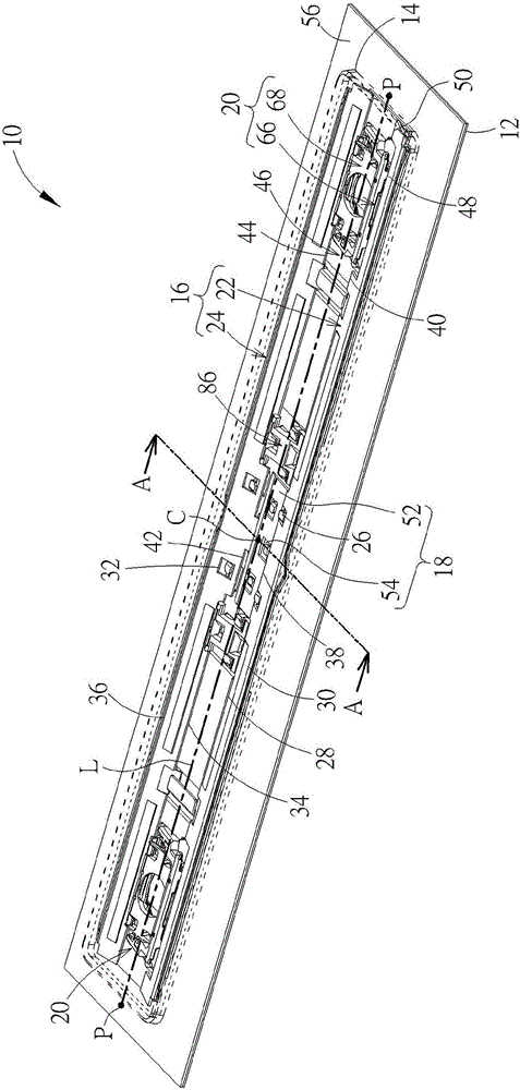
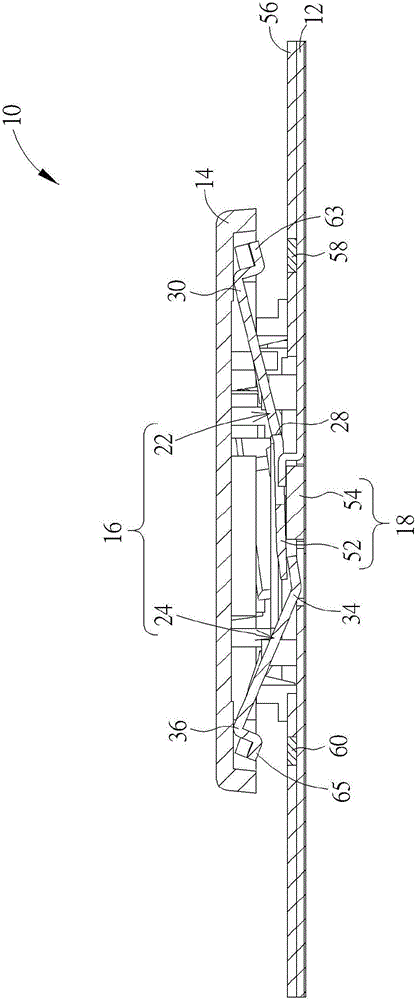
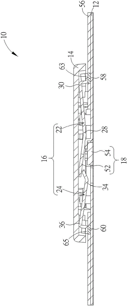
[0028] see figure 1 , which is a three-dimensional schematic diagram of the key 10 proposed according to an embodiment of the present invention, wherein in order to clearly show the internal mechanism design of the key 10, the key cap 14 is figure 1 It is shown in dotted line. Such as figure 1 As shown, the button 10 can preferably be a long button (also known as a multiple button). figure 1Two are shown in , but not limited to). The keycap 14 has a keycap major axis L. As shown in FIG. The lifting mechanism 16 is arranged between the bottom plate 12 and the keycap 14, and the keycap 14 moves between the pressed position and the unpressed position relative to the bottom plate 12 via the lifting mechanism 16. The lifting mechanism 16 includes a first plate-shaped bracket 22 and a second plate shape bracket 24. The first plate-shaped support 22 and the second plate-shaped support 24 are opposite to each other, and the first plate-shaped support 22 has at least one first rec...


PUM


Abstract

The invention relates to a key, which comprises a bottom plate, a key cap with a key cap major axis, a lifting mechanism, a spring-back device and a supporting mechanism, wherein the lifting mechanism is arranged between the bottom plate and the key cap and comprises a first plate-shaped support and a second plate-shaped support; the first plate-shaped support comprises a first side part and a second side part parallel to the key cap major axis for abutting against the bottom plate and the key cap respectively; the second plate-shaped support comprises a third side part and a fourth side part parallel to the key cap major axis for abutting against the bottom plate and the key cap respectively; part of the bottom plate enters accommodating openings of the first plate-shaped support and the second plate-shaped support to enable the first plate-shaped support and the second plate-shaped support to be movably connected onto the bottom plate; the spring-back device is used for driving the key cap to be returned to an un-pressed position along with pivoting of the first plate-shaped support and the second plate-shaped support relative to the bottom plate via the first side part and the third side part; and the supporting mechanism comprises a first supporting piece and a second supporting piece which are pivoted mutually to be movably connected between the key cap and the bottom plate. The pulling force of the key cap can be increased, and the problem that the key cap of a multiple key is likely to fall can be solved effectively.

Description

technical field [0001] The present invention relates to a key, in particular to a key that is movably connected between a keycap and a bottom plate by a support mechanism located between a first plate-shaped support and a second plate-shaped support to increase the pulling force of the keycap. Background technique [0002] As far as current personal computer usage habits are concerned, the keyboard is one of the indispensable input devices for inputting characters, symbols or numbers. Not only that, but all consumer electronic products in daily life or large-scale processing equipment used in the industry need to be equipped with a key structure as an input device to operate the above-mentioned electronic products and processing equipment. [0003] The distance of the up and down movement of the traditional key is longer, so it is easy to set the bowl-shaped rubber body under the key cap, so that when the key cap is pressed down, the bowl-shaped rubber body is also compresse...

Claims


Application Information

Patent Timeline
Patent Type & Authority Applications(China)
IPC IPC(8): H01H13/705
CPCH01H13/705H01H2221/04
Inventor 廖本辉林钦宏
Owner DARFON ELECTRONICS (SUZHOU) CO LTD
Why Eureka
Try Eureka