A temperature monitoring device and a power supply device

A monitoring device and battery module technology, applied in circuits, electrical components, secondary batteries, etc., can solve the problems of shortening the life of the battery module, inability to accurately detect the internal temperature of the module, etc., and achieve the effect of prolonging the service life.

Active Publication Date: 2020-05-26
HUATING HEFEI POWER TECH
View PDF4 Cites 0 Cited by
  • Summary
  • Abstract
  • Description
  • Claims
  • Application Information

AI Technical Summary

Problems solved by technology

[0003] In view of this, the object of the present invention is to provide a temperature monitoring device and a power supply device to improve the problem that the temperature sensing device of the existing battery module cannot accurately detect the internal temperature of the module, which leads to the shortening of the life of the battery module

Method used


Image

  • A temperature monitoring device and a power supply device
  • A temperature monitoring device and a power supply device
  • A temperature monitoring device and a power supply device

Examples


no. 1 example

[0044] For a first example, see Figure 1 to Figure 4

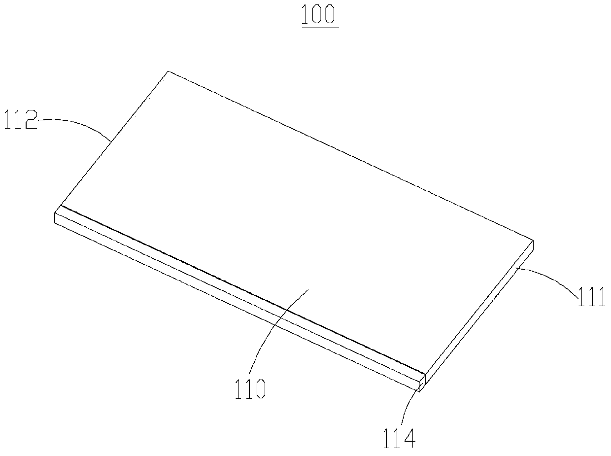
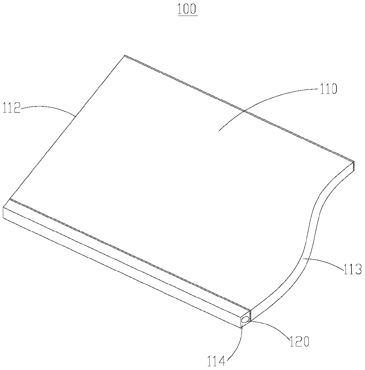
[0045] The temperature monitoring device 100 provided in this embodiment includes a liquid-cooled flat tube 110 and at least one temperature detection unit 120. For details, please refer to figure 1 The three-dimensional structural schematic diagram of the temperature monitoring device 100 shown and figure 2 The three-dimensional cross-sectional view of the temperature monitoring device 100 is shown. Wherein, the liquid-cooled flat tube 110 includes a liquid inlet 111 , a liquid outlet 112 , and a coolant circulation channel 113 communicating with the liquid inlet 111 and the liquid outlet 112 . The liquid-cooled flat tube 110 is further provided with a wiring groove 114 along the flow direction of the cooling liquid on one side of the cooling liquid circulation channel 113 , and the at least one temperature detection unit 120 is arranged in the first wiring groove.

[0046] Such as image 3 As shown in FIG. 1 , it is ...

no. 2 example

[0053] For a second example, see Figure 5 to Figure 10

[0054] The temperature monitoring device 100 and the power supply device 200 provided by the second embodiment of the present invention have the same realization principles and technical effects as those of the first embodiment. For a brief description, for what is not mentioned in the second embodiment, please refer to the first Corresponding content in the embodiment.

[0055] Figure 5 It is a three-dimensional structural diagram of the temperature monitoring device 100 provided in the second embodiment. Image 6 yes Figure 5 The three-dimensional cross-sectional view of the temperature monitoring device 100 is shown. Such as Figure 5 with Image 6 As shown, in this embodiment, the liquid-cooled flat tube 110 is provided with a wiring groove 114 on both sides of the cooling liquid circulation channel 113 along the flow direction of the cooling liquid, and the two sides of the liquid-cooled flat tube 110 are ...

no. 3 example

[0060] For a third embodiment, see Figure 11 to Figure 12

[0061] The temperature monitoring device 100 provided in this embodiment is different from the above embodiments in that the liquid-cooled flat tube 110 is not provided with the wiring groove 114 , but is provided with a plurality of installation parts 116 instead. Each of the installation parts 116 is used to install one of the temperature detection units 120 , specifically, the temperature sensor is disposed inside the installation part 116 , and the data transmission line is routed inside the battery module 210 .

[0062] There are many ways to set up the installation part 116. Optionally, such as Figure 11 As shown, a plurality of installation parts 116 are arranged at intervals on one side of the cooling liquid circulation channel 113, or as Figure 12 As shown, a plurality of installation parts 116 are arranged at intervals on both sides of the cooling liquid circulation channel 113, and even when the upper ...


PUM


Abstract

The invention provides a temperature monitoring apparatus. The temperature monitoring apparatus comprises a liquid-cooling flat tube and at least one temperature detection unit, wherein the corresponding temperature detection unit is in contact with the liquid-cooling flat tube for monitoring the temperature in a battery module; a power supply apparatus adopting the temperature monitoring apparatus comprises the battery module; the battery module adopts multiple single batteries; the multiple single batteries are divided into multiple layers of sub modules; each sub module layer comprises multiple single batteries; the liquid-cooling flat tube is arranged in the battery module; and at least one section of the liquid-cooling flat tube is positioned in the gaps between any two adjacent sub module layers. By adoption of the designed temperature monitoring apparatus and the power supply apparatus, the temperature of the batteries on the periphery of the battery module can be monitored while the internal temperature of the battery module can be effectively monitored as well; and when a condition of thermal instability occurs, the internal abnormal temperature of the battery module can be monitored in time and the region of thermal instability can be positioned accurately.

Description

technical field [0001] The present invention relates to the technical field of battery thermal management, in particular to a temperature monitoring device and a power supply device. Background technique [0002] At present, the temperature sensing device of the battery module can only detect the temperature of the peripheral single battery in the battery module. During the power supply process of the battery module, because the heat dissipation performance of the peripheral battery is better than that of the internal battery, the temperature sensing device There is a large gap between the measured temperature of the peripheral single battery and the actual temperature inside the battery module, especially when the temperature inside the battery module has exceeded the battery’s tolerance range, and the temperature of the peripheral battery measured by the temperature sensing device When the temperature is still in a normal state, the monitoring system will judge that the te...

Claims


Application Information

Patent Timeline
Patent Type & Authority Patents(China)
IPC IPC(8): H01M10/48
CPCH01M10/486Y02E60/10
Inventor 李树民苏俊松劳力周鹏
Owner HUATING HEFEI POWER TECH
Why Eureka
Try Eureka