co 2 Laser Live Wire Insulation Cutting System and Cutting Method

A live wire and insulation sheath technology, which is applied in the field of CO2 laser live wire insulation sheath cutting system, can solve the problem that the contact area between the puncture contact piece and the cable metal core is difficult to control, mechanical tools can scratch the metal cable core, and it is easy to cause personal injury and death accidents, etc. problems, to achieve the effect of realizing remote all-round monitoring, good skin cutting quality, and meeting the requirements of safety and craftsmanship

Active Publication Date: 2017-08-11
ANSHAN LANLING JIDIAN PROTECTION +2
View PDF5 Cites 1 Cited by
  • Summary
  • Abstract
  • Description
  • Claims
  • Application Information

AI Technical Summary

Problems solved by technology

[0004] The domestic 10kV power supply line live connection operation is a routine high-voltage live operation. It has gone through four technical stages: insulating gloves, insulating tools, insulating bucket trucks and robots. The first three stages are all manual live work. In the threat of electric field, the risk factor is high, which is likely to cause personal injury and death accidents. However, the live connection operation of the robot has no stress feeling when operating the lead wire cutting insulation skin tool, and the mechanical tool often scratches the metal cable core, so it cannot be widely used.
[0005] There is also a technical form of insulation piercing lead clip, which is also a direction for the development of live connection technology at present, but the puncture contact piece is limited by the material, and in the high voltage level live connection operation, it is difficult to face the insulation protection layer of high voltage cables. The density and thickness of the puncture contact piece and the contact area of ​​the cable metal core are not easy to control, and it is very easy to cause current overload and heat due to poor contact, and even fire accidents

Method used


Image

  • co  <sub>2</sub> Laser Live Wire Insulation Cutting System and Cutting Method
  • co  <sub>2</sub> Laser Live Wire Insulation Cutting System and Cutting Method
  • co  <sub>2</sub> Laser Live Wire Insulation Cutting System and Cutting Method

Examples


Embodiment Construction

[0041] The specific embodiment of the present invention will be further described below in conjunction with accompanying drawing:

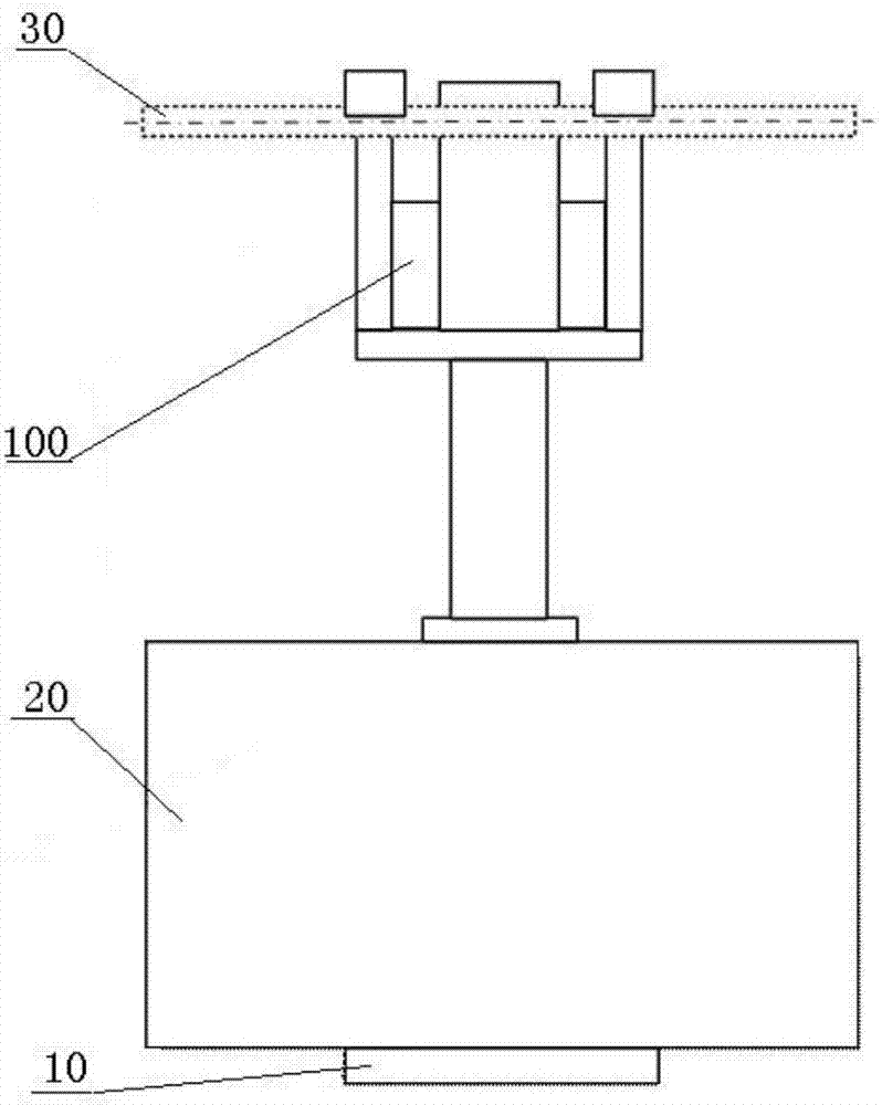
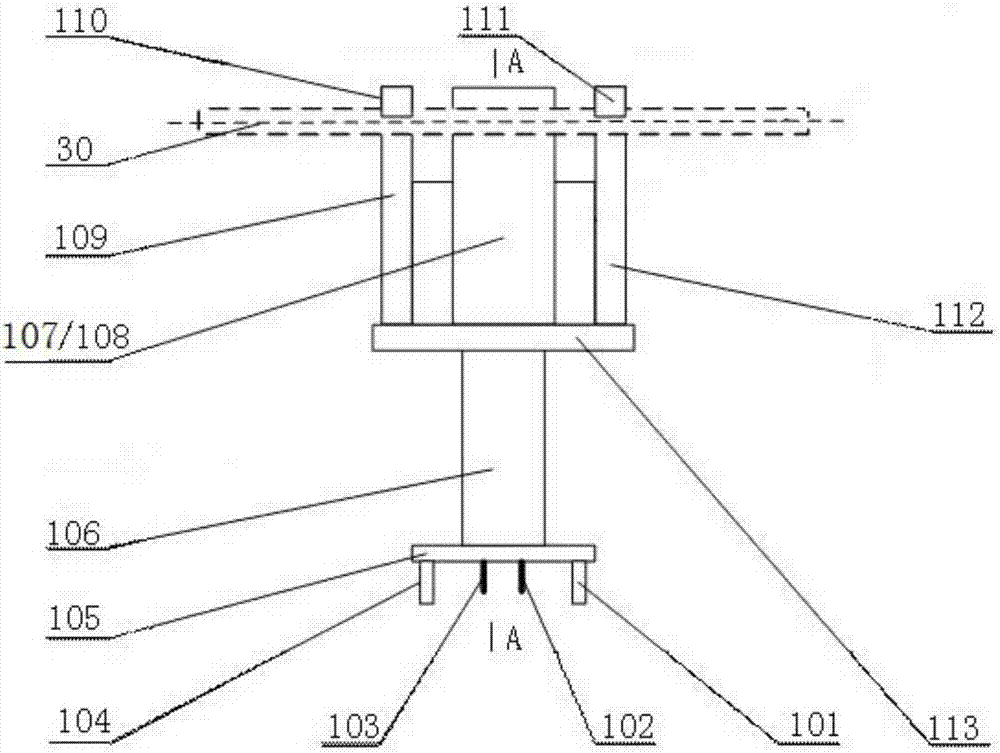
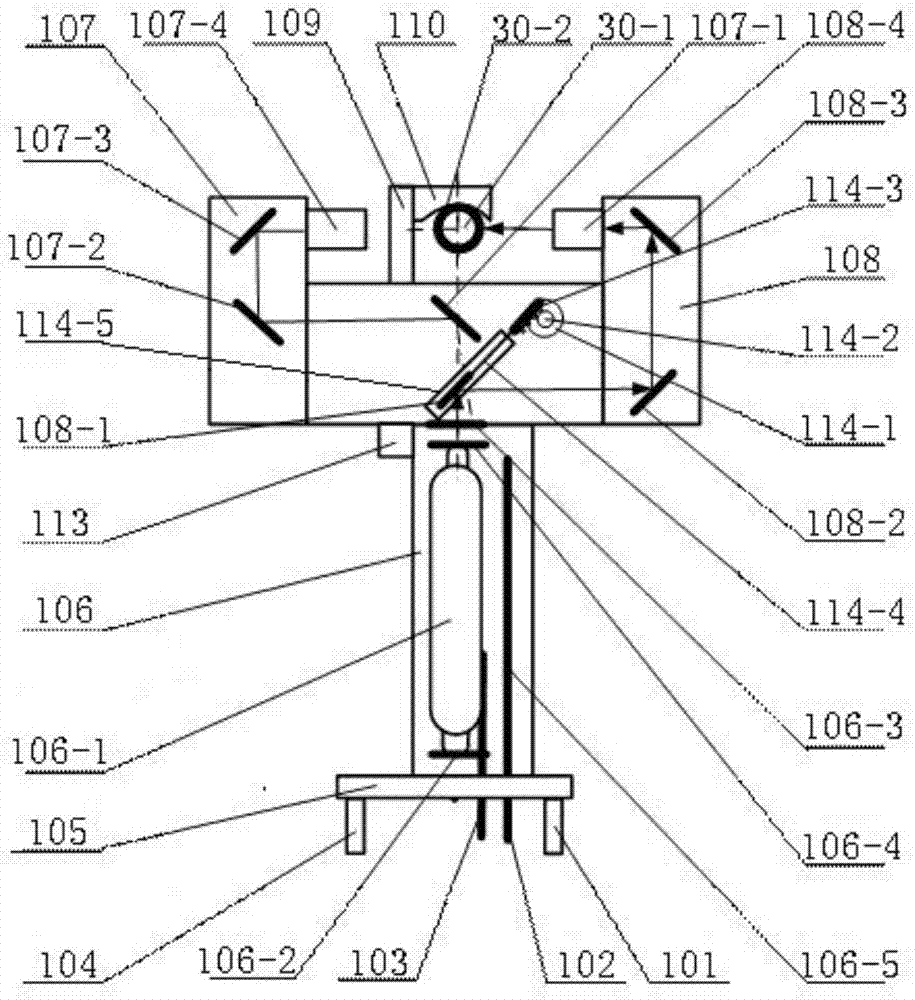
[0042] Such as Figure 1-Figure 6 As shown, CO 2 Laser live wire insulation sheath cutting system, including CO 2 Laser 106, left optical path system 107, right optical path system 108, control system and suspension mechanism, described left optical path system 107 and right optical path system 108 are arranged on the fixed crossbeam 113, are symmetrically suspended on both sides of live conductor 30 by suspension mechanism, CO 2 The laser 106 is arranged below the fixed crossbeam 113, and its laser beam emission port is facing the charged wire 30; the left optical path system 107 is composed of a left path reflector group and a left path galvanometer box 107-4, and is used for CO 2 The laser beam that the laser 106 sends is guided to the charged wire 30 side; 2 The laser beam that laser 106 sends is guided to the charged wire 30 other sides; ...


PUM


Abstract

The invention relates to a CO2 laser live conductor insulating sheath cutting system and method. A left optical path system and a right optical path system are symmetrically suspended at two sides of a live conductor through a suspending mechanism, and a CO2 laser is disposed below. The left optical path system consists of a left reflector group and a left galvanometer box, and the right optical path consists of a reflector group and a right galvanometer box. The first left reflector and the first right reflector are arranged vertically, wherein the lower one of the first left and right reflectors is provided with a reflector moving device. The CO2 laser, the left galvanometer box, the right galvanometer box and the reflector moving device are respectively connected with a control system. Through different physical burning characteristics of CO2 laser for rubber and metal and the guide effect of the galvanometer boxes on a laser beam, the double-optical-path system cuts H-shaped notches at two sides of the insulating sheath of a live conductor, and achieves the complete cutting of the insulating sheath through precise alignment. One CO2 laser is used for achieving the time-sharing operation of double optical paths, and can achieve the omnibearing remote monitoring.

Description

technical field [0001] The invention relates to the field of high-voltage live work, in particular to a CO 2 Laser live wire insulation sheath cutting system and cutting method. Background technique [0002] Power supply is the basic guarantee for maintaining social production and residents' life, and is an important pillar of national economic development. However, with the rapid development of the national economy and the continuous improvement of people's living standards, the power grid system has gradually become larger, and the expansion of the power grid has become more frequent, requiring frequent maintenance, new equipment installation, power connection and other construction in large quantities. As far as the 10kV power supply line is concerned, due to the long power supply line and the increase in power supply users, a power outage will cause immeasurable losses, especially in residential areas with dense high-rise buildings, the power outage information is often...

Claims


Application Information

Patent Timeline
Patent Type & Authority Patents(China)
IPC IPC(8): H02G1/12
CPCH02G1/128
Inventor 黄耀阳周培忠王彦明高振江刘君梁凯韩春成王春岩李叶军苏松
Owner ANSHAN LANLING JIDIAN PROTECTION
Why Eureka
Try Eureka