Power generation device and charging system

A technology for power generation devices and charging systems, applied in circuit devices, battery circuit devices, generators/motors, etc., can solve the problems of affecting heat conduction efficiency, low power generation efficiency, uneven heat conduction, etc., so as to avoid wasteful loss and improve power generation. Efficiency, the effect of improving heating efficiency

Active Publication Date: 2016-08-31
ZHONGXIA NEW ENERGY SHANGHAI CO LTD
View PDF1 Cites 5 Cited by
  • Summary
  • Abstract
  • Description
  • Claims
  • Application Information

AI Technical Summary

Problems solved by technology

[0007] The problem to be solved by the present invention is that in the prior art, the heat conduction efficiency is affected due to uneven heat conduction between the heating end and the hot end

Method used


Image

  • Power generation device and charging system
  • Power generation device and charging system
  • Power generation device and charging system

Examples


Embodiment 1

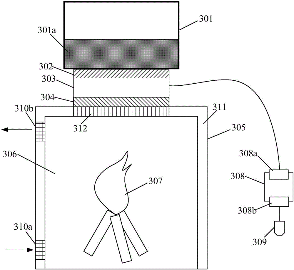
[0040] A structure of the power generation device provided by the embodiment of the present invention is as follows: image 3 As shown, the power generating device includes: a thermoelectric power generation part 303, a heat dissipation part 301, a heating part 305, a first heat conduction pad 302, a second heat conduction pad 304, a first electric energy output part 308 and a power supply interface 309; A thermal pad 302 includes a first surface and a second surface, the first surface and the heat dissipation end of the heat dissipation component 301 (ie image 3 The bottom of the heat dissipation component 301 (not shown in the figure) is bonded, and the second surface is bonded to the cold end of the thermoelectric power generation component 303; the second thermal pad 304 includes a third surface and a fourth surface , the third surface is bonded to the hot end of the thermoelectric power generation component 303, and the fourth surface is bonded to the heating end 312 of ...

Embodiment 2

[0051] In the existing technology, such as figure 2 The thermoelectric power generation device shown only allows the output of electric energy by means of combustion and heating to realize power supply. The power supply method is single, and the use is not flexible enough, because in some cases, it is difficult to find suitable combustion materials in time, but electricity is urgently needed. For this reason, this embodiment is further improved on the basis of Embodiment 1 to provide another structure of the power generation device, such as Figure 4 As shown: in addition to the various components introduced in Embodiment 1, the power generating device also includes a second electric energy output component 313 connected to the power supply interface 309, which is used to accommodate the energy storage component 314 and control the energy storage The component 314 releases electric energy and realizes external power supply through the power supply interface 309 .

[0052] Du...

Embodiment 3

[0056] Apply the power generating device in Embodiment 2 or 3 to charge the batteries in electrical equipment such as mobile phones, GPS, smart bracelets, etc., to ensure the battery life of these electrical equipment, which is one of the most important uses in the field environment . For this reason, based on the power generating device in the second or third embodiment, this embodiment also provides a charging system, such as Figure 5 As shown, the charging system includes: a target battery 40 to be charged, a charging device 50 suitable for charging the target battery 40, and the above-mentioned power generating device 30, the power generating device 30 is connected to the charging device 50 for use To provide power for the charging device 50 .

[0057] In this embodiment, in order to realize the charging of the target battery 40 by the power generating device 30 more efficiently, in addition to improving the power generation efficiency of the power generating device 30 i...


PUM


Abstract

The invention relates to a power generation device and a charging system. The power generation device is composed of a thermoelectric generating component, a heat radiating component, a heating component, a first heat conductive gasket, a second heat conductive gasket, a first electric energy output unit and a power supply interface. The first heat conductive gasket includes a first surface and a second surface; the first surface is in contact with a heat radiating end of the heat radiating component; and the second surface is in contact with a cold end of the thermoelectric generating component. The second heat conductive gasket includes a third surface and a fourth surface; the third surface and a thermal end of the thermoelectric generating component are in contact; and the fourth surface and a heating end of the heating component are in contact. The first heat conductive gasket and/or the second heat conductive gasket employ/employs flexible materials/ a flexible material that can store energy and has a good uniform heat transferring performance. The first electric energy output unit connected with the thermoelectric generating component is used for outputting the electric energy generated by the thermoelectric generating component and carrying out external power supplying through the power supply interface. According to the technical scheme, uniform heat radiation during the heat conduction process can be guaranteed; a local high temperature phenomenon can be avoided; and the heat conduction efficiency and power generation efficiency can be improved.

Description

technical field [0001] The invention relates to the technical field of power generation and charging, in particular to a power generation device and a charging system. Background technique [0002] Thermoelectric power generation, also known as thermoelectric power generation (generating electricity by thermoelectric), is a green and environmentally friendly power generation method. Its basic principle is to use the temperature difference between the contact points of two conductors to generate electromotive force (Seebeck effect) to generate electricity directly. Thermoelectric power generation technology is a technology that uses thermal energy to directly generate electricity. Compared with traditional power generation methods (turbogenerators), it has simple structure, strong and durable, no moving parts, no noise during operation, no waste emissions, and easy to use. With a series of advantages such as long life and high reliability, it is an environmentally friendly po...

Claims


Application Information

Patent Timeline
IPC IPC(8): H02J7/32H02N11/00
CPCH02J7/32H02N11/002
Inventor 潘凡峰
Owner ZHONGXIA NEW ENERGY SHANGHAI CO LTD
Why Eureka
Try Eureka