Exhaust steam recovery system

A spent steam recovery and steam technology, applied in the field of spent steam recovery system, can solve the problems of no automatic adjustment function, high maintenance cost, fixed efficiency of mechanical vacuum pump, etc.

Active Publication Date: 2013-12-25
CROWN CHEMICAL CORP
View PDF5 Cites 2 Cited by
  • Summary
  • Abstract
  • Description
  • Claims
  • Application Information

AI Technical Summary

Problems solved by technology

The existing exhaust steam recovery devices mainly use mechanical vacuum pumps to extract exhaust steam. Although this type of recovery equipment recovers exhaust steam, it has the following disadvantages: 1. It consumes a lot of electric energy to drive the vacuum pump; 2. The efficiency of mechanical vacuum pumps is relatively low. Fixed, does not have automatic adjustment function, and enterprises with large fluctuations in steam consumption cannot use it; 3. High maintenance costs

Method used


Image

  • Exhaust steam recovery system
  • Exhaust steam recovery system
  • Exhaust steam recovery system

Examples


Embodiment Construction

[0013] The present invention will be further described below in conjunction with the accompanying drawings.

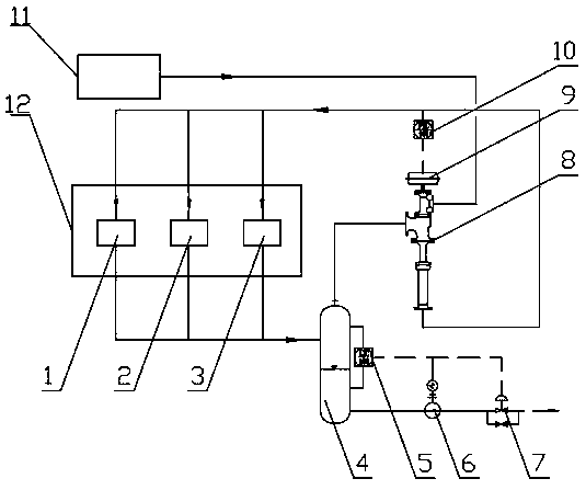
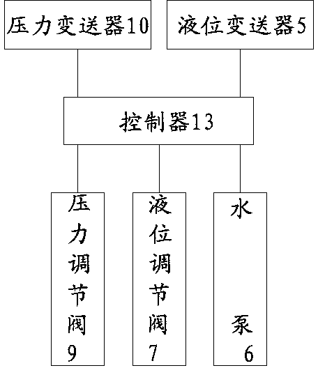
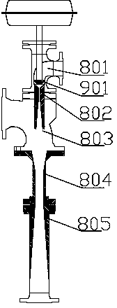
[0014] As shown in the figure, a exhaust steam recovery system includes a exhaust steam recovery pump 8 and a pressure regulating valve 9. The exhaust steam recovery pump 8 and the pressure regulating valve 9 may be of an integrated structure or may be of a separate connection structure. The exhaust steam recovery pump 8 includes a steam inlet assembly 801, a exhaust steam suction chamber 803, an expansion throat pipe 804 and an expansion pipe 805 connected in sequence. The lower end of the core 901 is equipped with a Laval nozzle 802 , and the Laval nozzle 802 is arranged through the steam inlet assembly 801 and the exhaust steam suction chamber 803 .

[0015] The working principle of the exhaust steam recovery pump 8 is as follows: in the adiabatic state, the regulating valve core 901 in the steam inlet assembly 801 controls the working steam to pass through the Lava...


PUM


Abstract

The invention relates to an exhaust steam recovery system and belongs to the technical field of chemical devices. The exhaust steam recovery system comprises an exhaust steam recovery pump and a pressure regulating valve. A steam inlet assembly pipeline of the exhaust steam recovery pump is connected to a power station steam network. An expanding pipeline of the exhaust steam recovery pump is connected to a user side. A user side pipeline is connected to a flash tank. One pipeline of the flash tank is connected to an exhaust steam intake chamber of the exhaust steam recovery pump. The other pipeline of the flash tank is connected to a condensate recovery mechanism. The pressure regulating valve is controlled through a controller. The controller is in signal connection with a pressure transmitter used for detecting pressure of the pipeline between the exhaust steam recovery pump and the user side. The exhaust steam recovery system is simple in structure and reasonable in design; while heat energy of power station steam is not lost, steam from steam condensate is recovered, and pressure relief using relief valves causes waste of the steam from power stations in the prior art is avoided; based on 50t of daily steam consumption, about 300,000 Yuan of economic benefit can be produced yearly.

Description

technical field [0001] The invention belongs to the technical field of chemical equipment, and in particular relates to a exhaust steam recovery system. Background technique [0002] At present, with the gradual increase of the implementation of the national energy saving and consumption reduction policy, exhaust steam recovery devices have begun to appear for exhaust steam recovery. The existing exhaust steam recovery devices mainly use mechanical vacuum pumps to extract exhaust steam. Although this type of recovery equipment recovers exhaust steam, it has the following disadvantages: 1. It consumes a lot of electric energy to drive the vacuum pump; 2. The efficiency of mechanical vacuum pumps is relatively low. Fixed, does not have automatic adjustment function, and enterprises with large fluctuations in steam consumption cannot use it; 3. The maintenance cost is relatively high. Contents of the invention [0003] Aiming at the problems existing in the prior art, the ob...

Claims


Application Information

Patent Timeline
Patent Type & Authority Applications(China)
IPC IPC(8): F28B9/10
Inventor 杨宗泽向玉
Owner CROWN CHEMICAL CORP
Why Eureka
Try Eureka